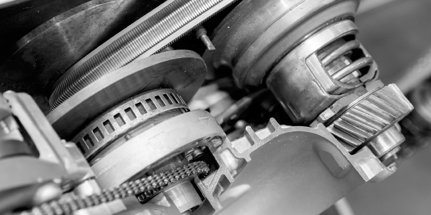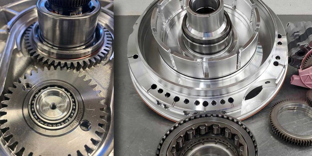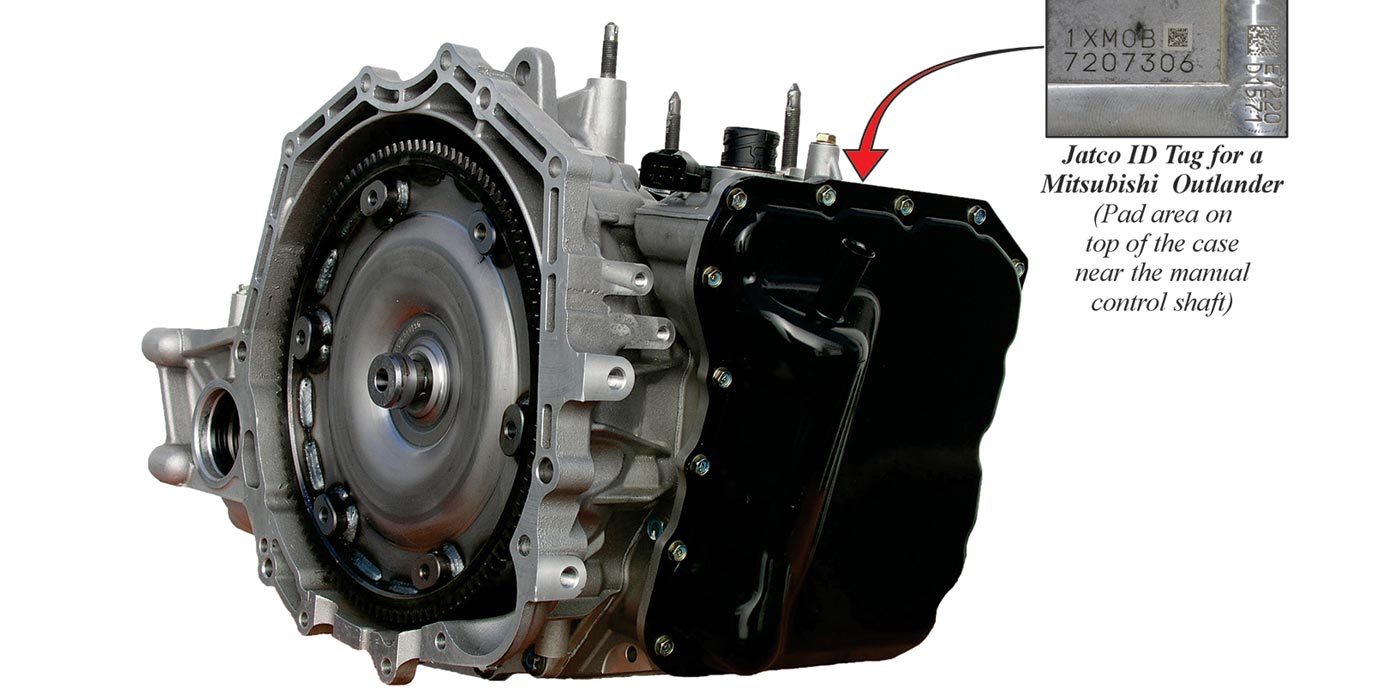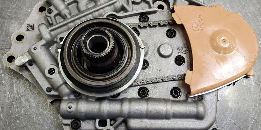
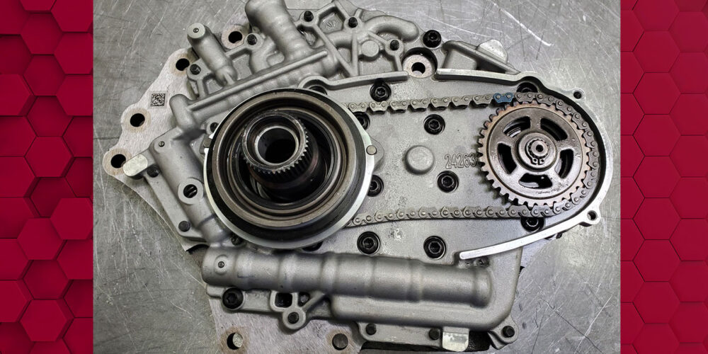
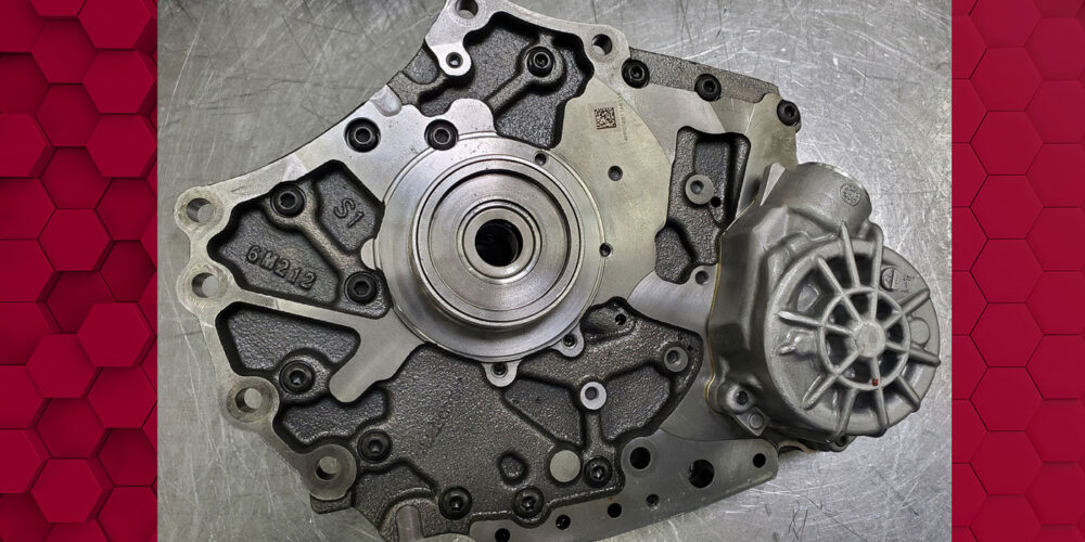
For the past several years, GM has used a binary positive displacement vane type pump. The compact design allows for it to be utilized in off-axis applications such as the 8L90 transmission and the third generation 6T40 transmission. Figures 1 (above) through 4 display a view of this style pump in the 6T40 applications.
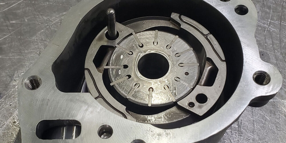
The cam ring is stationary and elliptical in design, sitting in a housing with dual suction and pressure output ports. Not only does this design allow for on-demand flow of volume, it also keeps the rotor balanced, preventing side-loading of the pump drive shaft. With the absence of vane rings, pressure at the center of the cam is used to push the vanes outward to seal against the cam. In time, these vanes wear into the cam, causing a loss of pump pressure.
Read more columns from our Shift Pointers series here.
Russel Mott at AACTION Transmissions encountered this recently with a 2017 Chevy Impala 2.5L that came in with slightly over 100,000 miles to its name. When the selector lever was placed into reverse, the engine would need to be revved up to get it to move. In forward, it would slip. Code P2723 was set for a performance problem with PCS 5 which is used to regulate pressure for the 1-2-3-4 Clutch. When the unit was out and apart, the low pressure caused damage to the transmission. The cam wear was not seen at first so when the unit was rebuilt and put back into the vehicle, the problem remained.
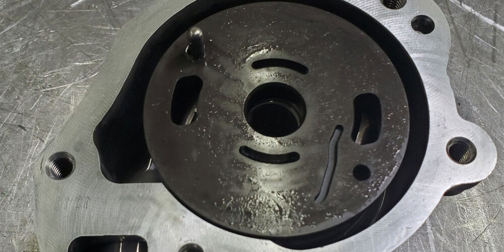
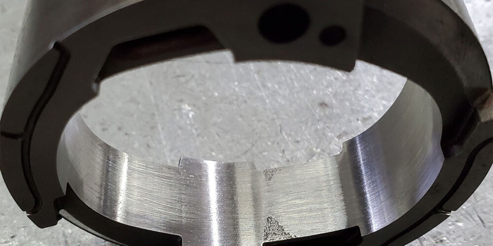
The unit was pulled and a completely different “used pump assembly” was put in. This pump assembly includes the stator support, drive chain and pump that is seen in Figure 1. Once the unit was back in the vehicle, the problem remained. The unit was pulled and gone through again but could see nothing as the pump itself was not fully disassembled. This time, they put in a new pump assembly which resolved the loss of pressure issue. When the pumps were completely disassembled and inspected, sever wear on the inside of the cam ring was discovered, as Figure 5 shows.
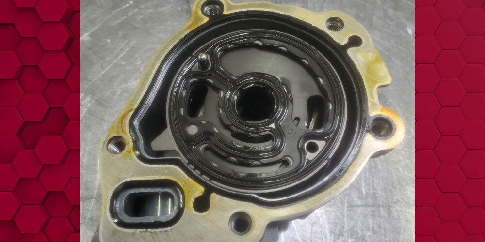
During reassembly of this pump, be sure to have the dot on the rotor and cam facing up as seen in Figure 4. Use Figure 6 to see how the pressure plate is properly installed on top of the rotor and cam. And then use the updated rubber coated fluid pump seal as seen in Figure 7.