Tech to Tech
- Subject: Recurring TCC code
- Vehicle Application: Toyota RAV4
- Essential Reading: Rebuilder, Diagnostician
- Author: Jeff Bach
Solenoid creates confusion in diagnosing problem
When I get a vehicle from a shop that specializes in transmissions and has exhausted its resources, it’s a good bet that the problem is not going to be a simple one.
This particular shop is a chain store that has a technical-support department. I had the opportunity to work with one of its tech-support people on this 2000 Toyota RAV4 that had a torque-converter-clutch (TCC) code that kept recurring.
The code chart for the P0770 shift-solenoid-E malfunction has a simple description of the diagnostic trouble code (DTC) checking condition: It says that the lockup does not occur during lockup range (50 mph) or lockup remains on during lockup-off range. The possible causes listed are that the shift-solenoid valve is stuck open or closed, the valve body is blocked or stuck, or the clutch is locked up.
The transmission had a new clutch, a new valve body from the dealer, and several shift solenoids had been installed. With all the logical hard-part testing done, the electrical system was suspected, and that’s when I got the vehicle.
Since I’ve been seeing more and more electrical problems with transmissions lately (and they can get pretty tricky in complexity to diagnose), I like to start with the basics and make sure the transmission is getting proper solenoid action from the solenoids that shift it before I go on to the TCC or pressure-control systems.
This truck uses two solenoids to get all four gears. When I want to see the transmission operation on these two solenoid-shifted transmissions, I like to see the solenoid current at one second per division on the scope. This lets me drive the vehicle and see the two solenoid current levels during all the shifts.
On this Toyota, the easiest access is the powertrain control module (PCM). I can pull the glove box and check all the necessary transmission controls simply by probing the circuits right out of the PCM. To see these shift solenoids, I put both solenoid control circuits through a current probe on one scope channel. This is possible because the current probe doesn’t tap into the electrical circuit; it senses the magnetic field surrounding the circuit and converts it to a voltage signal that can be viewed with the scope. I use the second scope channel to see one of the two solenoid voltage signals.

I can tap into this circuit and get an actual voltage reading directly from the circuit. With this combination I can tell which solenoid is being energized and when (Figure 1).
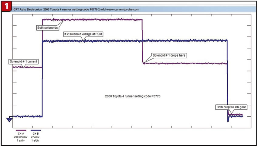
I used the voltage signal from the No. 2 solenoid for this test. From this diagram I can see that solenoid No. 1’s current is occurring during first-gear operation, both solenoids are energized for second gear, and only the No. 2 solenoid is on for third and fourth and is in limp mode or neither solenoid energized.
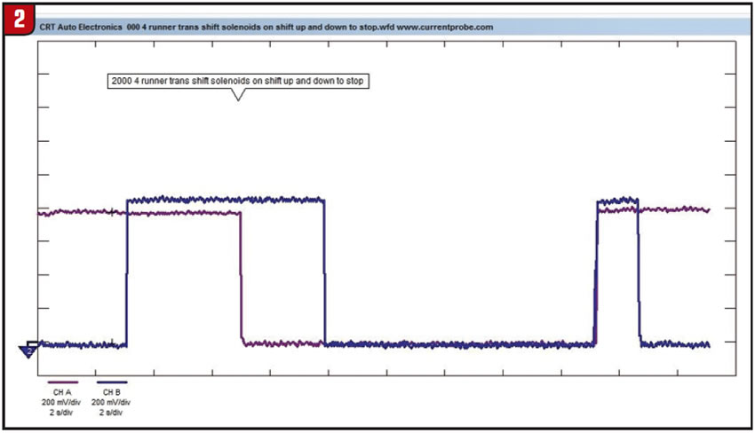
By stretching the time base and putting a current probe on each solenoid, I can see the downshift pattern (Figure 2). From this pattern I can see that this transmission downshifts from fourth gear straight to second and then drops into first.
Knowing that the transmission shift solenoids’ electrical circuits are intact from the info gathered, I would like to see a blowup of the solenoids to be sure of their physical condition.
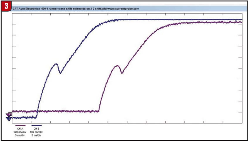
The fact that both solenoids come on during downshift as the vehicle comes to a stop lets me set the scope to five milliseconds per division and see both solenoids current on the screen for comparison (Figure 3). Both solenoids appear to be working with no sign of shorting.
The next thing I wanted to do was see what was going on with the TCC electrical circuit. For me, the best way to see this circuit is to check both the voltage and the current at the same time. To see these signals, I connect one scope lead to the PCM TCC control wire to monitor the voltage signal. Next, I connect my current probe around the same circuit on the lab scope’s other channel.
Figure 4 shows the result of my test drive of the two signals while commanding the PCM to energize the TCC solenoid (shift solenoid E) with the scan tool.
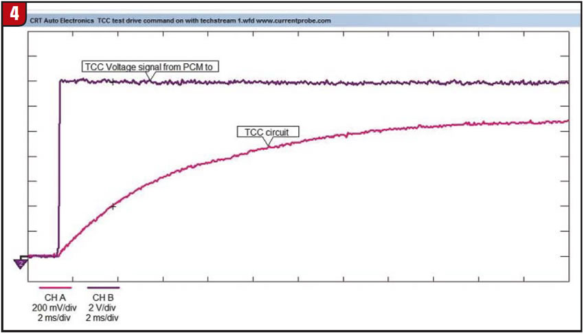
The voltage signal out of the PCM is a full 14 volts, and the current is just more than 1 amp with a nice inductive curve reaching full current in about 20 milliseconds.
This confirms the integrity of the complete electrical circuit for the solenoid, including the ground. What looks odd, though, is the fact that there is no movement of the solenoid’s plunger. This was the first TCC solenoid I’ve seen for this model vehicle, but from my experience if there is movement in any solenoid due to plunger operation it will show up in the inductive curve as an obvious deflection. I knew that making the statement that the solenoid was defective – knowing that this was one of multiple TCC solenoids installed in this transmission – would be controversial at minimum.
I decided to double-check the way this solenoid was supposed to operate. For example, was it normally closed and the current opened it, or was it normally open and the current closed it?
The factory test for the solenoid showed that it was normally closed and should hold 71 psi of air pressure and that when current was applied, the pressure should release. This caused me to believe that the solenoid plunger should pull against the spring pressure and open, causing the waveform deflection I was looking for – unless, of course, it needed the additional pressure to work against the spring with the current to open the valve. I told the transmission-shop owner what I had found and requested that one of the solenoids previously replaced be used to test my theory. They later brought me a new one from the dealer, so I did comparison testing.
When I looked at the waveforms side by side with and without air pressure, I decided that there could be the chance that there was no fluid pressure exerting force on the solenoid or that the solenoid was sticking (Figure 5).
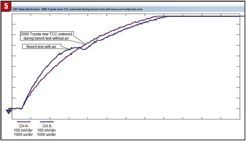
With the information about this system that I have acquired through my testing, I make the call that the solenoid plunger is not moving either because there is not enough fluid pressure against the valve to help push the solenoid against the spring pressure or the solenoid itself is sticking.
The transmission shop picked up the vehicle and took it back to the shop. They decided to try one more solenoid on it before tearing it back apart. The owner of the shop called me to report that they did find that the solenoid was sticking and the new solenoid took care of the problem.
I liked getting this call, since it’s a little different when you have to be sure enough to send a vehicle out after doing your best to diagnose it, rather than getting to fix the problem in house. Either way, it’s still fun solving these challenges.
Jeff Bach is the owner of CRT Auto Electronics, an ASA-member shop in Batavia, Ohio. For more information on this topic, contact Bach at 515-732-3965. His e-mail address is [email protected] and his website is www.currentprobe.com.
This copyrighted article is reprinted with the permission of AutoInc., the official publication of the Automotive Service Association (ASA). To learn more about ASA and its commitment to independent automotive-service and repair professionals, visit www.ASAshop.org or call 800-272-7467.