
TASC Force Tips
- Author: Dan Tucker
What is it with the transmission industry? We’ve given up on English and moved to an alphabet soup of abbreviations. Like the military, our technical jargon has turned into a few numbers or letters. Let’s just hope for the sake of the transmission industry that in the future none of the automakers names a transmission AWOL (absent without leave) as the zero-emissions vehicles roll off the line.
TAPS is one of the latest acronyms to join the list. It stands for transmission adaptive pressure systems, and it is used both for shift adapts, which establish pressure control during the shift, and for steady-state pressure control, the adapting-pressure requirements for a given gear after the shift is completed.
Let’s look at the transmission shift adaptive-pressure system on the 4T65-E transaxle as an example. When I first read about the 4T65-E, I thought it was simply a 4T60-E with an electronic line-pressure control system using a pressure-control solenoid (PCS) instead of a modulator-controlled line-pressure system using a vacuum modulator. Although this is true, when it comes to the software operating this transaxle, it is far more complex than just a line-rise system.
With a 4T65-E, the powertrain control module (PCM) has the ability to direct the pressure-control solenoid (PCS) to increase and lower line pressure as needed and is programmed to monitor and adapt the strategies used for a variety of shift conditions. I’m sure many of you are aware that adaptive shift strategy is not new to GM. It has been out for more than a decade now, but on most GM vehicles the TAP systems have really evolved in the past few years.
As you can track with your scan tool, GM has given us the ability to monitor the adaptive state of the TAP cells for the individual upshifts. The individual cells for that shift, identified as TAP cell 4 up to TAP cell 16, represent different levels of demand by the driver: TAP cell 4 represents a light-load easy takeoff, compared with TAP cell 16, nearly a wide-open-throttle or heavy takeoff. The computer will monitor inputs such as load, vacuum or throttle position and do a programmed calculation to select which TAP cell is in use by the driver.
The enhanced shift-pressure control of the TAP system comes from its ability to continually fine-tune or adapt the original program strategy on a cell-by-cell basis. Each time the transaxle makes a shift, the PCM calculates the shift time and determines whether that particular TAP cell delivered an acceptable shift time. If not, the PCM will calculate the needed adjustments and either reduce or increase line pressure by changing the planned PCS amperage for the next time the PCM commands the same shift at the same TAP cell. The adaptive data shown on the scan tool is the increase or decrease in pressure compared with the originally programmed pressure target. The average maximum and minimum adjustments the PCM can make are normally between -29.75 psi and +29.75 psi either side of the original pressure. It is really quite simple and a great system, as the PCM has the ability to make minor adjustments to compensate for all the variables a transmission can have inside it.
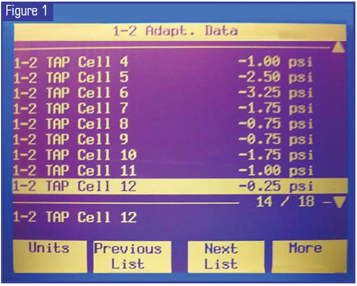
On the 4T65-E you have adapt data for the 1-2, 2-3 and 3-4 shifts. Figure 1 shows the typical 1-2 adapt-data cells on a 4T65-E that is working correctly. As you can see, most of the TAP-cell adaptives are within 3 psi of their program base pressure. There is also a nice relative consistency if we look at it as a cell-to-cell comparison.
Take a look at Figure 2 and you will notice that for the 1-2 shift adaptives for this unit, TAP cell 6 is at 12.50 psi, TAP cell 7 is -19.50 and TAP cell 8 is -7.50.
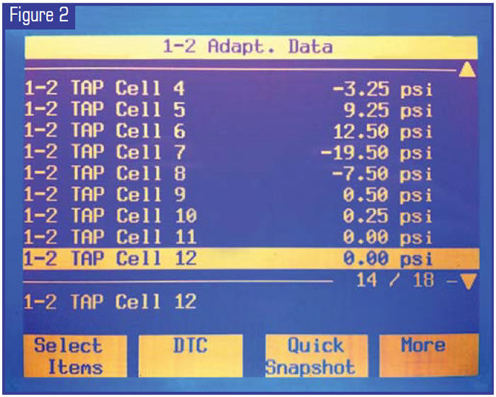
This is not a normal set of adapt-data TAP-cell values. First off, cells 6 and 7 stand out as a much wider adaptive than the other cells. Additionally, the swing in adding or reducing pressure is substantial and erratic as we look cell by cell. It is hard to come up with a reason as to why the PCM would be changing the pressure that much from one TAP cell to the next one.
Here is where the data becomes a valuable tool. The 1-2 adapt data in Figure 2 is from a vehicle that came into our shop for a cracked, noisy flywheel. It had no trouble codes and the transaxle worked great. Before we pulled the unit out we quickly checked the TAPs and discovered these readings. This led us to believe that the transaxle had a real problem controlling pressure. With this in mind we looked at the other adapt data for the 2-3 and 3-4 shifts. There, again, we noted several cells with an even greater adaptive change than in the 1-2 data, some of which were approaching the adaptive max but had not triggered DTC P1811 (Maximum Shift Adapts Exceeded), and we saw a similar, noticeable pattern of inconsistency as we compared cell to cell. Clearly, pressure control was an issue.
So in this instance checking the TAPs pointed us toward, at the very least, replacing the pressure-control solenoid (PCS ) while we had the transaxle out to replace the cracked flywheel. This is indeed what we did, and after we replaced the PCS, we reset the TAPs with the scan tool. On the road test after about 10-15 upshift cycles I checked the TAPs again. Go back to Figure 1: That was actually from the same unit after the repair. You can see a major change for the good, which we also saw on a recheck of the 2-3 and 3-4 adaptives.
Another important concern with the TAPs is to always reset them after you have done any major transmission/transaxle repair work. If you have a PCM that has been adapting to long shifts from a burned clutch, burned band or internal leak, it has compensated by raising the TAP pressure. If you don’t reset the TAP after you make the repair, expect a harsh shift. Not knowing this and failing to reset the TAPs may lead you to unnecessary work such as chasing down a harsh shift after a well-executed repair. The system will adapt to the repaired operation of the unit over time, but this can take many drive cycles. The desired adapt value after a repair most likely will be far closer to the zero point than the pre-repaired value that had adapted to a problem.
You will get to the new value more quickly if you reset, and at the same time you will avoid “building in” a temporary new condition such as a harsh shift. The fastest way to reset the TAPs is with a scan tool. However, not all scan tools have the reset feature. If your scan tool doesn’t have the reset ability, you can try disconnecting the battery for a long period (usually it takes more than 30 minutes).
Changes in the design and methods used to control today’s automatic transmissions continually challenge us to increase our understanding and refine our diagnostic methods. Although TAP control systems certainly require that we understand a different approach to pressure control, they also are providing us with information that can be extremely useful in our diagnoses. Understanding and paying attention to shift adaptive pressures is only one method for using the information we can gain from TAPs.
Next month, in Part 2 of this article, we’ll look at steady-state adaptive pressures and how you can find and use even more information.

Dan Tucker owns Tucker’s Transmission in Pine Bluff, Ark., and is a member of the TASC Force (Technical Automotive Specialties Committee), a group of recognized industry technical specialists, transmission rebuilders and Sonnax Industries Inc. technicians. ©2005 Sonnax


