TASC Force Tips/Torque Converter Tech Tips
- Subject: Converter overheating
- Vehicle Application: Honda
- Essential Reading: Rebuilder, Diagnostician
- Author: Ed Lee
Editor’s Note: Whether you see things as ending with the turbine shaft or beginning with the input shaft, this problem has caused you time, money and a great deal of aggravation.
Overheated Honda converters have become a living nightmare for many transmission and torque-converter shops, one that has lingered way too long because of the many misconceptions and missteps during the problem-solving process. The blame game has gone back and forth, but the torque-converter rebuilders have been receiving most of the criticism.
The overheated converters have been pushing the frustration levels of many transmission rebuilders to an all-time high. Shopping around for a different torque-converter rebuilder was common during this period. At one point, ATRA technical adviser Mike Souza said that many of his tech calls would start with the question, “Is there anyone out there that can build a good Honda converter?”
The reality is that if the proper converter friction material for the clutch-application strategy was being used (such as BorgWarner HTS for models with a modulated TCC), the clutch-release clearance was adjusted properly (0.035 inch is correct for most models) and the TCC circuit seals were doing their job, there was not much more that the torque-converter rebuilder could do. The painful truth is that the torque-converter rebuilder could supply a great converter and still have an overheating issue. The fact that at least half of the overheated Honda converters in any given core pile are OE converters is further proof that the problem was not being caused by rebuilt converters.
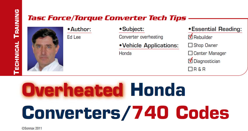
The appearance of the converters after a failure (Figure 1), and the fact that most failures ended with a P0740 code, led to the misconception that the failures were caused by heat.
Consequently, a lot of time was wasted focusing on the inside of the converter instead of working to increase the volume of oil flowing through the converter.
Why was the converter overheating?
Many transmission shops helped to find the root cause of the overheating issue, but ATEX Transmissions in Port Richey, Fla., stands out for its effort. The shop manager, Sean St. John, logged hundreds of road-test miles with vehicles equipped with flow-monitoring devices to record cooler flow and strategically placed pyrometers to record temperatures. Sean was the first person to recognize that after warm-up, when the vehicle would come to a stop, the cooler flow would drop to zero. The flow would resume when the idle was raised above 1,200 rpm.
Most important, he noticed that the temperature of the oil exiting the converter would increase dramatically when the cooler flow dropped to a certain level.
Sean’s observations led to the conclusion that the heat in the converter was caused by the clutch dragging on the cover during periods of low TCC-charge (release) oil flow and not as a result of slipping during TCC application, as previously thought. But why was the low flow happening? This became easier to understand when a pressure gauge was added and transmission line pressure was monitored at the same time as cooler flow. If the line pressure dropped at the same time as the cooler flow was decreasing, you would be looking for conditions such as low fluid level, severely worn valve bores or possibly a severely worn pump. But, since the line pressure remained high when the flow rate decreased, an out-of-position PR valve was more likely the cause of poor cooler flow.
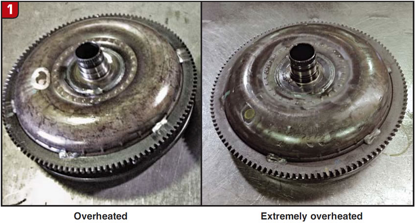
Typically, the PR spring and any available boost pressures push the PR valve in one direction and balance pressure opposes or pushes from the opposite direction until the valve reaches its regulating position. When the PR valve approaches its regulating position, charge oil (TCC-release oil) begins to flow and continues to flow as long as the valve remains in the regulating position (Figure 2).
In many systems, a modest base line pressure is established by the PR springs, with higher pressures coming as a result of some demand-related boost system. As you can see in Figure 2, Honda does not use a conventional line-pressure boost system. In the Honda system, more-substantial PR springs and a stator load-related boost system establish a much higher base line pressure from the outset with modest boost increase at max pressure.
Why was the cooler flow low?
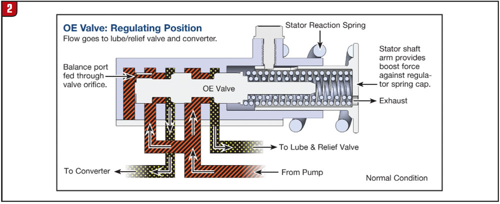
Under low-pump-output conditions, balance line pressure cannot overcome the stout PR spring and boost force. This causes the PR valve to move out of its regulating position (also referred to as a PR valve being “out of balance”). Under this condition (Figure 3), although line pressure is available (as noted by Sean), the valve has stroked over and shut off flow to the converter-charge/cooler circuit. The result: TCC dragging on the cover, little or no cooler flow to control that heat, and all those cooked converters in your core pile.
Why was the pump output low?
There are several factors that contribute to or hasten the occurrence the low-output/out-of-balance condition:
- Low pump capacity: A key factor is the low capacity of the Honda pump. Because the pump is designed around fuel-efficiency concerns and limited space restraints, it has very little reserve capacity. The higher the operational demands on the pump, the more likely it is that you will experience an overheated converter. The vehicles with the larger-diameter converters, larger clutch-drum capacities and more gears will be more likely to have converter overheating. Low pump capacity also makes wear an important factor. Pump wear, valve-bore wear and end-plug wear caused by high mileage will increase the likelihood of a converter overheating. Because of the delicate balance of the Honda PR valve, very little wear is necessary to upset this balance.
- Added demands on the vehicle: The chance of converter overheating also is present when there are added demands on the vehicle. Towing a trailer, overloading the vehicle or climbing over a mountain all will put added force on the stator in the converter and affect the balance of the PR valve.
- Oil viscosity: The viscosity of the oil also can be an issue. Since the viscosity of the oil is related to its temperature, the higher the ambient temperature, the higher the likelihood of an overheated converter. High-quality synthetic oil may be helpful, but since the Honda 1-2 shift feel relies so heavily on OE Honda fluid, it is less of an option.

Why doesn’t the engine stall?
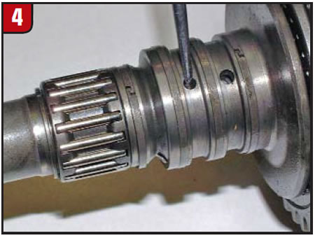
One question that always comes up is, “With the PR valve out of balance, why doesn’t the engine stall when the flow of charge oil is so low and the clutch is dragging?” This is an excellent question, and the answer involves the type of hydraulic lockup circuit that the Honda uses. The two-path lockup circuits on the E4OD and rear-wheel-drive three-speed Chrysler transmissions have both had engine-stall problems caused by flow issues. If Honda had a two-path lockup circuit, it probably also would have an engine-stall issue. The lockup circuit found on Honda transmissions is a three-path circuit that uses a bypass valve like some front-wheel-drive Ford transmissions. The three-path lockup circuit is not as susceptible to engine stall as the two-path circuits because there are two checkvalves that can be forced open before full lockup is achieved. One downside to the three-path lockup circuit is that there are more areas for potential leaks. The Honda primary-charge-oil circuit enters the input/turbine shaft between the second and third sealing rings (Figure 4) and exits at the end of the shaft between the cover and TCC clutch.
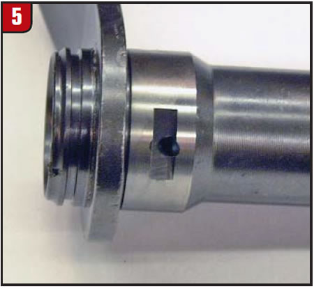
This circuit is generally fairly tight. The parallel circuit, on the other hand, does not have a positive seal where the stator support passes through the valve body (Figure 5).
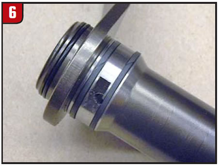
This parallel circuit is prone to leak and does have some effect on flow. Not all shops will be able to address this leak, but the overheated-converter issue can be resolved without fixing this leak. If you are able to address this leak (Figure 6), you will add about 0.2 gallon per minute to your cooler flow.
Addressing the low-flow/out-of-balance issue
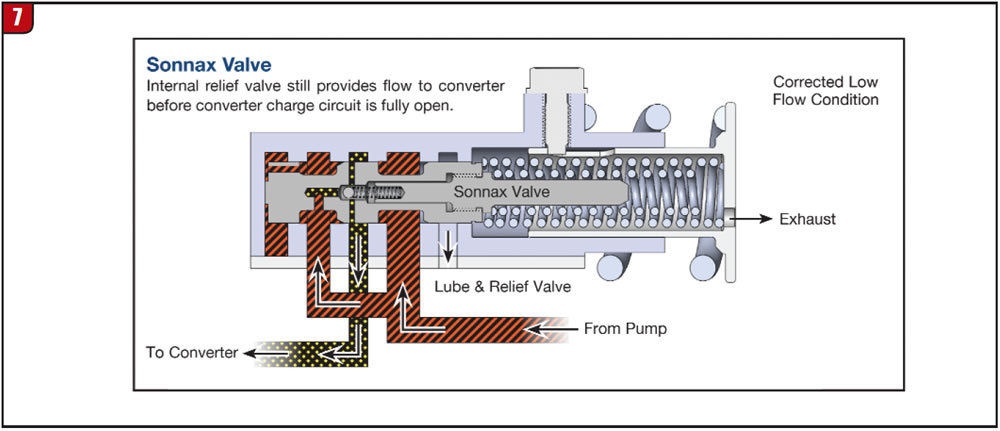
Since there is little or no flow of converter-charge oil to keep the TCC piston from dragging on the cover when the PR valve is out of balance, you will need to create an alternate or secondary path for oil flow. For an effective repair, you should consider an aftermarket PR valve with a built-in, metered, line-to-lube circuit. This allows flow to the converter and cooler when the valve is out of balance but does not affect flow when it’s in the regulating position.
In addition, a checkvalve prevents converter drain-back when the engine is shut off. Remember that the root cause of the converter overheating is low pump capacity, and you do not want to make this issue worse by creating a drain-back condition. Starting a Honda and have it starve for oil because of drain-back will only create more pump wear and lead to lower pump output, which only makes the root cause of the problem worse. Figure 7 shows the Sonnax lube-regulated pressure-regulator valve 98892-04K for Honda four-/five-speed units, maintaining flow during the out-of-position situation.
For further reading, refer to the “Anatomy of a Transmission” article in the Sonnax Transmission Technical Library at www.sonnax.com or the “Ford Bypass Converter Clutch Circuits” article on pages 98-99 of the Sonnax Transmission Specialties Catalog Volume 5 and in the Sonnax online tech library.
Ed Lee is a Sonnax technical specialist who writes on issues of interest to torque-converter rebuilders. Sonnax supports the Torque Converter Rebuilders Association. Learn more about the group at www.tcraonline.com.
©Sonnax2011


