Technically Speaking
- Author: Wayne Colonna, Technical Editor
The VT20/25-E CVT transaxle, otherwise known simply as VTi, is a transmission built in the Fiat GM Powertrain Plant in Hungary and is on the road in the United States in Saturn’s Vue SUV and in the Ion Quad Coupe.
The Vue had a late production run of about 2,500 units in 2002, but between the two models from 2003 to present, about 82,000 of these units were produced. On Jan. 6, 2004, GM stopped production of this transmission, blaming durability issues with the steel belt that could have an effect on a small percentage of these vehicles. Production resumed in mid-March with the Ion Quad Coupe, followed by continued production of the Vue in May. In an attempt to offset the negative impact this incident may have caused and to increase customer confidence, GM lengthened its warranty from the original three years/36,000 miles to five years/75,000 miles.
The steel push belt is a critical component in a continuously variable transaxle and a major reason why CVTs are not used behind large-displacement engines. The largest to date in the United States is with the Nissan Murano, and it is doing well behind the 3.5-liter V-6 engine. As the steel-push-belt technology increases, so will the displacements of the engines that drive them. As CVTs are more compact with fewer parts, they offer increased fuel economy by having greater engine torque efficiency with a pleasability factor of a smooth drive. The benefits are certainly there for the manufacturer.
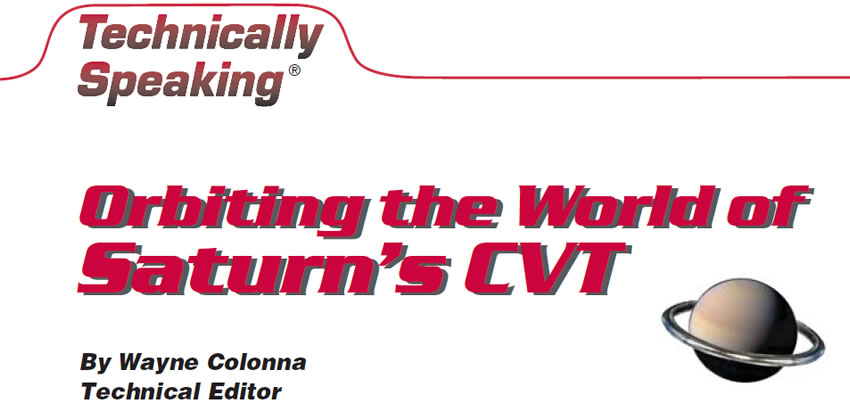
So what are some of the issues a manufacturer confronts when making a CVT with a steel push belt? Let’s take the Vue as an example. The steel belt used in this unit is the same-style belt used in the Honda Civic HX. Developed by Van Doorne Transmissie (VDT) of the Netherlands, it is now in the control of Robert Bosch Corp. The difference between the belts is in the width and the number of elements used. Honda uses a 24mm-wide belt with about 280 elements; Saturn uses a 30mm belt with about 472 elements. All these elements are held together with 12 steel bands (see Figure 1).
Since we are orbiting Saturn’s belt issue, we can eliminate the myth that these belts stretch. They do not. Instead, they wear at the contact point on the sheaves (pulley faces). The evidence that this has occurred is that material from the elements has been transferred to the sheaves.
The question arises, “What makes a belt slip?” Several possibilities are available: low pressure in the pulley chambers, the type and condition of the fluid, or input torque higher than what the belt is rated for. These are a few of the basic issues a manufacturer confronts when designing a CVT with a steel push belt.
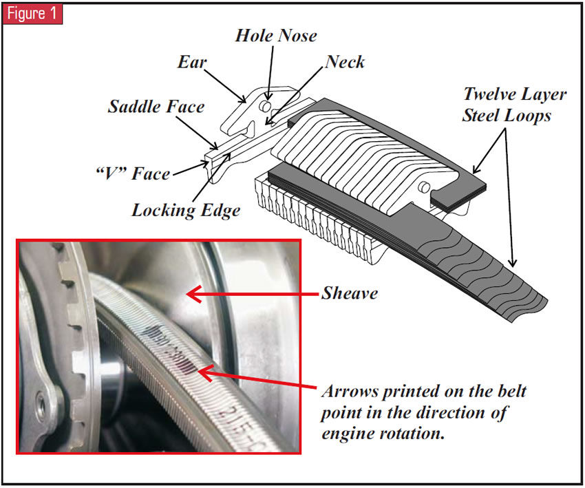
Looking at the VTi’s belt and pulley set in Figure 2, this would be the approximate starting point of the CVT with a 2.61 launch ratio. In this configuration, about 53 elements are making contact with the pulley face on the wrap angle of the drive pulley, while on the wrap angle of the driven pulley, about 270 elements are making face contact.
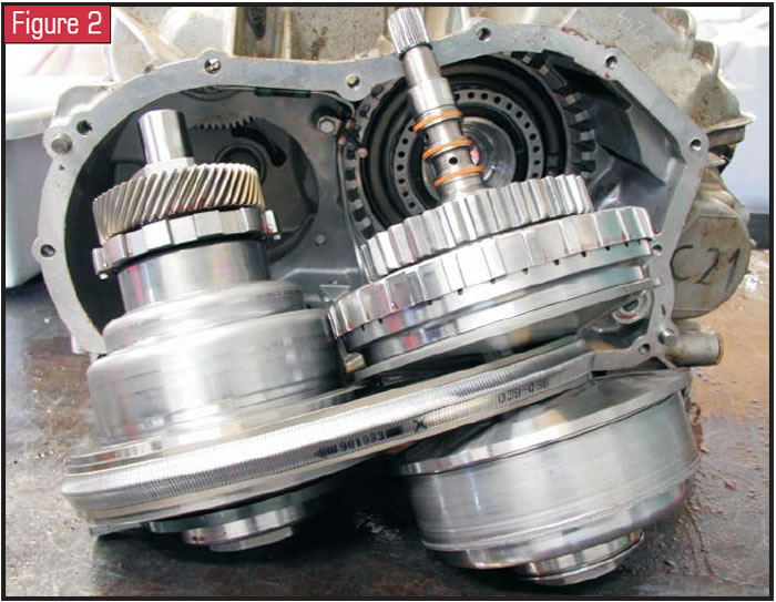
Now, let’s start throwing in some extra ingredients. The pump shown in Figure 3 needs to provide 51 bars, or 740 psi, of pressure for the pulley system at idle and above. The Vue is about 1,500 pounds heavier than originally intended. With this extra weight, it is underpowered by its 2.2-liter four-cylinder engine. Uh-oh! Additionally, this VTi uses a conventional lockup torque converter, which multiplies torque on take-off. The belt is rated for 220 nm of torque, and the torque converter through engine torque management in the multiplication mode can input to the transmission about 220 nm. So, if the pump is marginal, or pressure is down for any other reason, a slip of the belt is sure to occur and will be noticed on take-off. If pressure loss is at a minimum, as soon as the transmission begins to increase the drive-pulley radius, more elements are gained on the wrap and the slip drifts away.
Generally speaking, the VTi is most vulnerable to belt failure on initial takeoff. The engine speed picks up from an idle, when pump volume was down; torque multiplication begins to occur in the torque converter; and the drive-pulley radius places the belt at a tight wrap angle. Any slipping during this 2.61 initial launch ratio usually can be attributed to low hydraulic-system pressure. A restricted filter, a weakened spring in the pump’s blow-off-valve assembly, excessive pump wear, improper operation of the related valves and electronics in and on the valve body, or leaks in the pulley apply circuits would be a brief laundry list of dirty pesky possibilities. Another consideration is that the VTi requires a specific fluid called DEX-CVT®. If an incorrect fluid is used, and in this instance let’s say Dexron III®, the coefficient will be wrong and the fluid may churn like butter.
Now that we have orbited the belt issue, let’s land on the control center of Saturn’s VTi, where the surface is flat on the module leadframe (see Figure 4).
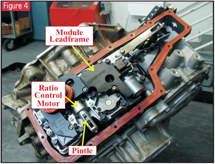
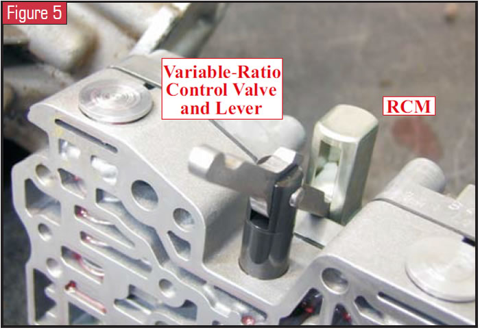
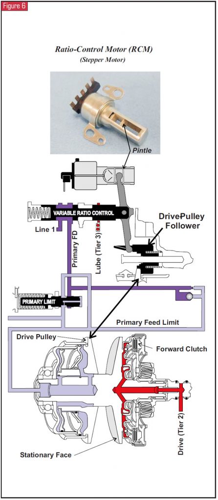
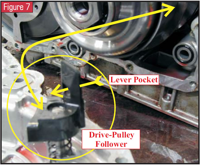
There staring us in the face is the bi-directional ratio-control motor (RCM). This is an electrical device that is more familiarly known as a stepper motor. It consists of five terminals and two coils that electrically rotate a threaded shaft to which a pintle is attached. The RCM receives commands from the TCM to change the transaxle ratio from a low of 2.61 to a high of 0.44 and back again by rotating the threaded shaft extending and retracting the pintle. The pintle is keyed to a lever that is attached to a valve in the valve body called the “variable-ratio control valve” (see Figure 5). The linear movement of the pintle moves this valve in and out of its bore to accurately feed fluid into the primary-pulley piston (drive pulley) which controls the various drive ratios (see Figure 6). At the opposite end of the variable-ratio control-valve lever is the drive-pulley follower (see figures 6 and 7). This spring-loaded follower rides on the movable drive-pulley half and reacts to the movement of the drive pulley as it changes ratios. With one end of the lever being in the ratio-control motor and the other end being in the drive-pulley follower, the follower acts as a movable pivot point for the lever. In doing so, it becomes a mechanical sensor influencing the variable-ratio control valve tailoring the feed fluid into the drive-pulley piston.
To perform a dynamic test of the RCM (stepper motor), supply battery voltage to the center terminal marked number 3 in Figure 8. Alternate a ground repeatedly between terminals 1 and 4 and watch the pintle move away from the coil. For every 10 pulses the pintle will move about 0.89mm (0.035 in.). The RCM has a total nominal travel of 22.0 mm. Keeping a battery supply to the center terminal marked 3, alternate a ground repeatedly between terminals 2 and 5 and watch the pintle move in toward the coil. Do not leave current flowing through the stepper for great lengths of time or damage may occur (In other words, do not hold the ground on a terminal for more than a second). When the TCM performs this alternating ground task, it is referred to as steps or counts and it sends a count once every 25 milliseconds (40 counts per second).
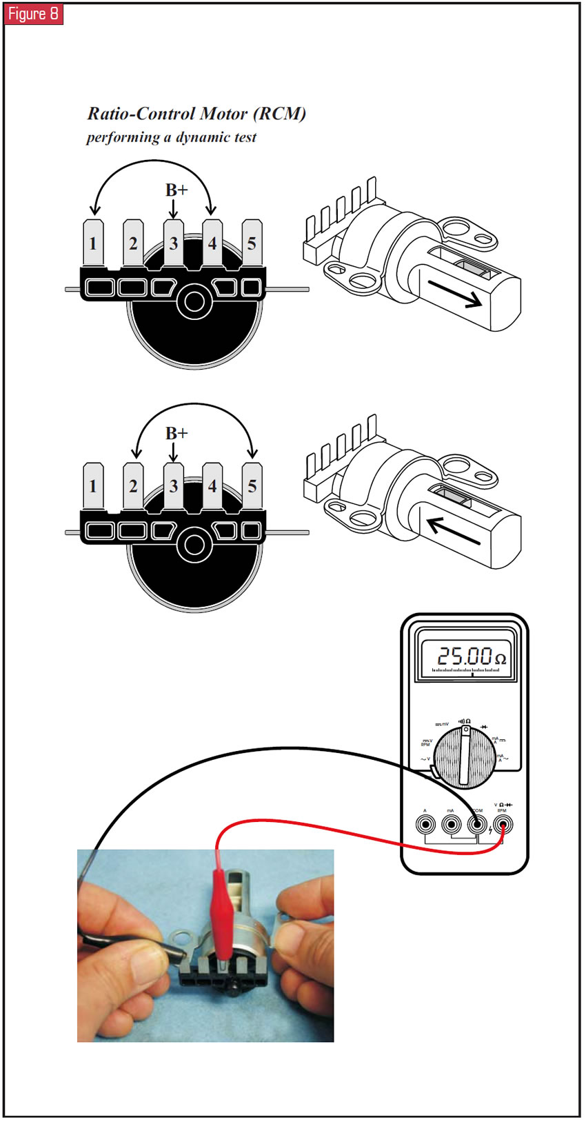
To perform a resistance check of the RCM, place the positive lead to the terminal marked 3 and with the negative lead make individual contact with terminals 1, 2, 4 and 5. Each should have about 25 ohms of resistance.
Although the drive-pulley follower acts as a mechanical sensor tailoring ratio, the input-shaft-speed (ISS) sensor and the output-shaft-speed (OSS) sensor are main inputs to the TCM for ratio control via the RCM (see Figure 9). Now it would be good to note that the TCM has the “ability” to change the VTi’s ratio from full high to full low in a second’s time. But on vehicles without antilock brakes, after a panic stop the vehicle will have remained in the ratio it was in before the stop, and this would be noticed on takeoff. A transducer monitoring drive-pulley pressure would be an additional input that the TCM could use to overcome this little glitch.
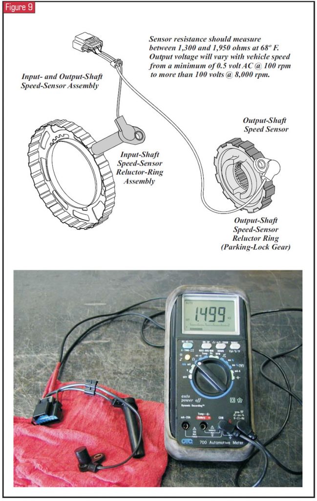
The speed sensors themselves also have had issues. Bulletin number 04-07-30-001 speaks of speedometer-fluctuation concerns. The fluctuation may occur at highway speeds, with the vehicle experiencing a hesitation condition. The fluctuation also may occur during a stop, in Park or Neutral, or even during takeoff in Drive. The cause of this is a conductive foam emulsion that accumulates on the inside of the top pan. (Just as with a Saturn TAAT, the VTi’s valve body sits on top of the transmission with a module leadframe connecting to the solenoids, with the main connector protruding from the pan). This conductive foam drips down onto the module leadframe and could short the circuitry for the speed sensors, resulting in an erratic speedometer. There is now a new-design speed-sensor set that incorporates an integrated bi-directional zener diode that protects the speed-sensor circuitry from these foam-induced spikes or irregularities. The part number at the time of this article is 24229640.
Figure 9 also shows resistance checks of these sensors, and you may notice the same thing I did. Look at how the ISS and OSS wires come very close to each other near the connector that plugs into the module leadframe. Do you think a little frequency interference could occur here?
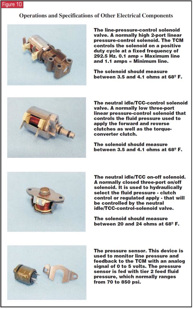
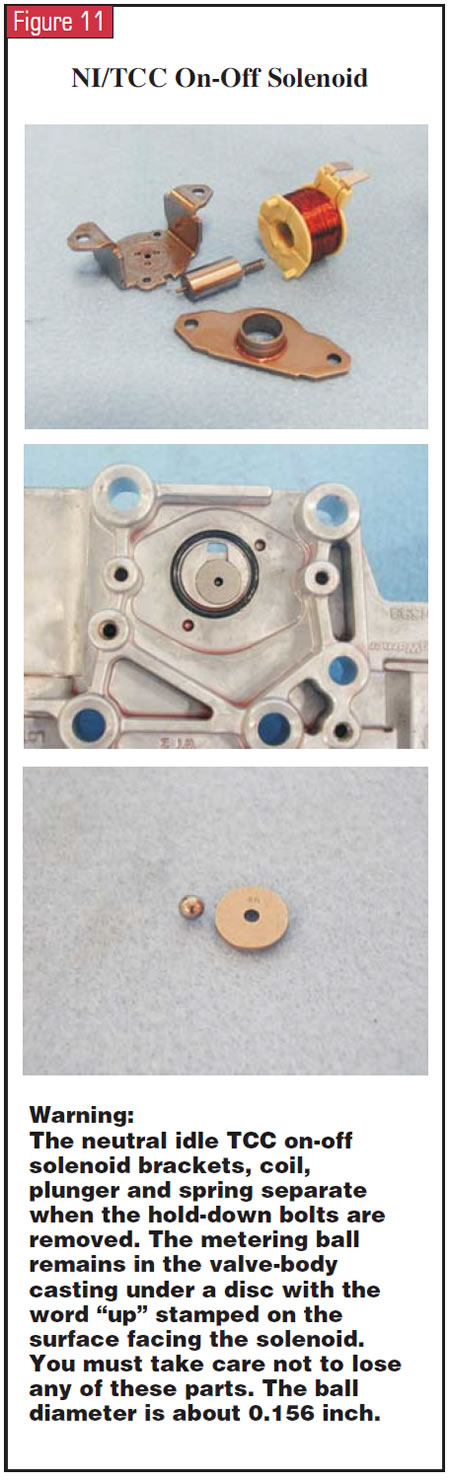
Figure 10 gives you a brief overview of the functions of the solenoids used in this CVT and their resistance checks. You must be careful when handling the neutral/idle on-off solenoid as you can see in Figure 11. The solenoid brackets separate and the coil, spring and plunger fall away. This solenoid’s seat location on the valve body has a directional disc that has under it the ball the solenoid uses to open and close the actuator-feed-limit circuit to the TCC/NI enable-signal circuit. The disc has the word “UP” stamped into it for proper positioning, and the ball measures 0.156 inch in diameter.
When this vehicle is in Park or Neutral, a line-pressure pulse takes place to clean the solenoids. Owners may mention a hissing or chirping noise as a result of this. A reflash procedure is available to lower the line pressure during this cleaning process. Refer to bulletin number 04-07-30-005 for details.
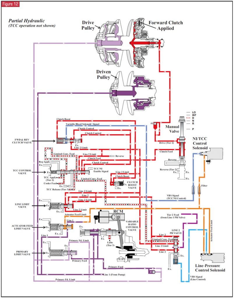
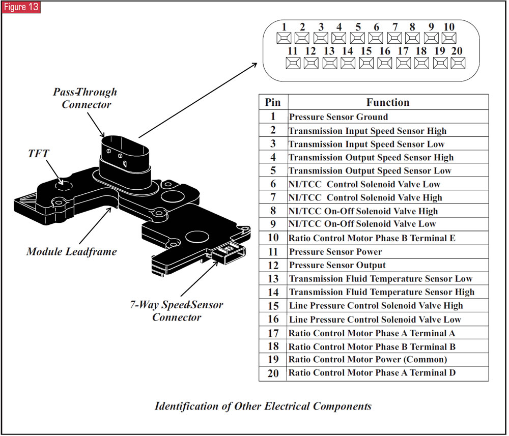
Well, our orbiting time is up, and it’s time to head back to earth. For future visits, Figure 12 provides a pin-out for all the solenoids and sensors internal to the VTi through the module leadframe for external inspections. Figure 13 is a hydraulic schematic for a broader view of the drive- and driven-pulley circuits.
Scotty, where are you?
Thanks to SPX Corp. for the use of its VTi and for Thom Mendola’s taking the time out of his schedule so I could take these photographs.


