Technically Speaking
- Subject: Function of the multi-select solenoid
- Unit: Chrysler 45RFE, 545RFE
- Essential Reading: Rebuilder, Diagnostician
- Author: Wayne Colonna, ATSG, Transmission Digest Technical Editor
The shift strategy of Chrysler’s 45RFE and 545RFE transmission is clever and unique. The computer controls a total of seven solenoids in the transmission to perform all shift-feel, shift-timing, converter-clutch-apply and failsafe strategies. The solenoids are:
- Line-pressure control (NA)
- Underdrive (NA)
- Overdrive (NV)
- Second clutch (NV)
- Fourth clutch (NV)
- Low/reverse (L)-TCC (NV)
- Multi-select (NA)
You will notice that I placed either NA or NV next to each of the solenoids listed. NA identifies the solenoid as being normally applied, and the NV indicates the solenoid is normally vented.
This means that should all electronic controls be taken away from the solenoids (like unplugging the solenoid harness or a failsafe condition), the three normally applied solenoids will apply pressure to their respective circuits and the four normally vented solenoids will vent their respective apply circuits.
As a result, the line-pressure control solenoid will produce maximum line pressure, the underdrive solenoid will apply the underdrive clutches, and the multi-select solenoid, which is the subject of this article, will apply one of three clutch circuits.
The multi-select solenoid is properly named, as it provides multiple tasks both in the shifting operation of the transmission and in the failsafe strategies of the transmission, which makes this solenoid very interesting. And by understanding its function, should its operation fail, you can quickly identify the effects.
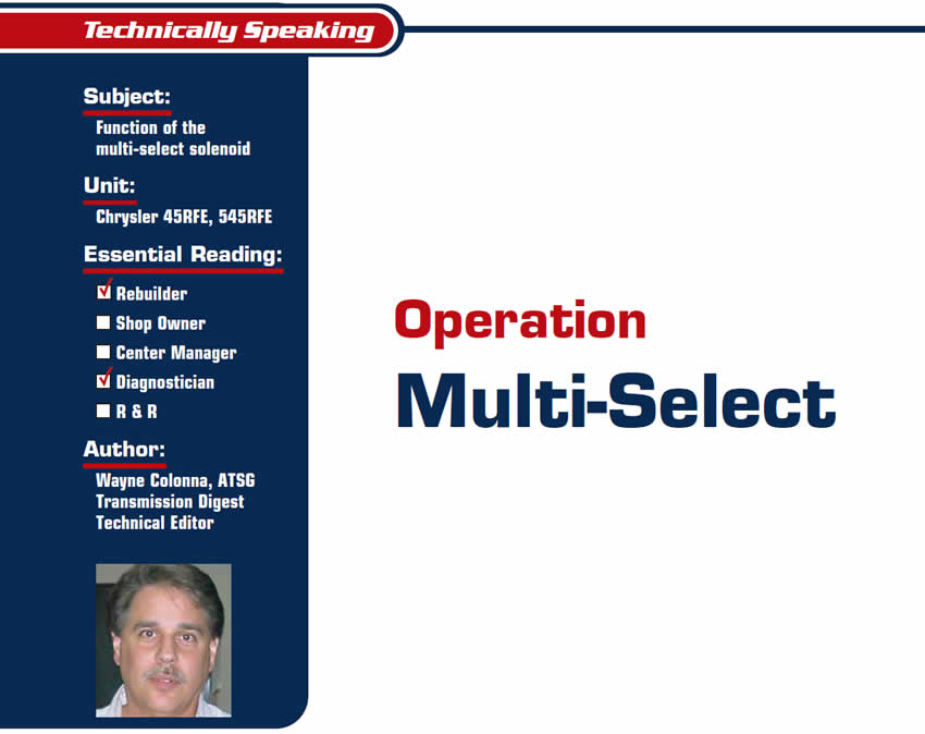
When the transmission is working correctly, this solenoid is energized in every range except for reverse, 3rd and 4th gears. And since this solenoid applies pressure to its respective circuit when it is turned off, when the selector lever is placed into reverse, the manual valve will route the multi-select solenoid pressure to control the apply of the low/reverse clutch (see Figure 1). The reverse clutch is applied via the manual valve.
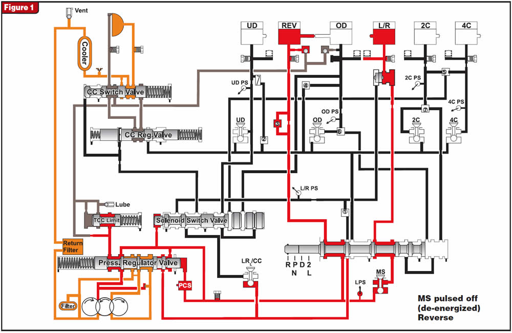
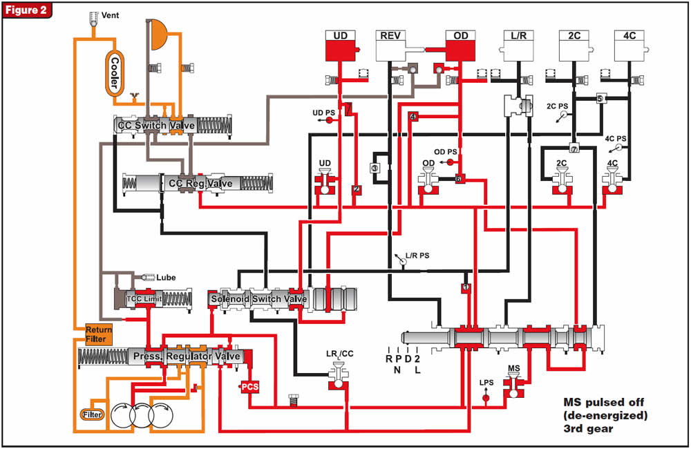
When the selector lever is placed into the drive range, the computer turns on the multi-select solenoid by energizing it, causing the solenoid to block its respective pressure circuit. The computer will turn this solenoid off when it is time to make the 2-3 shift, so the solenoid will now pressurize and apply the overdrive clutch (see Figure 2). As you can see by comparing the reverse hydraulic schematic in Figure 1 with the drive 3rd gear hydraulic in Figure 2, it was the position change of the manual valve that allowed this solenoid to apply a different clutch circuit. Figure 3 shows the solenoid as it remains in the applied state for the shift from 3rd to 4th.
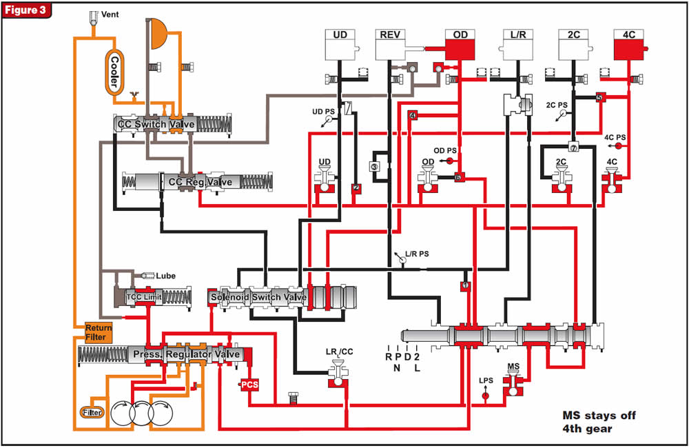
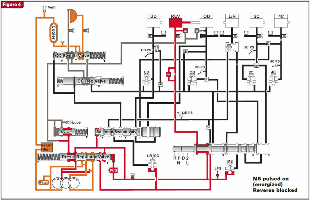
For failsafe strategy, this solenoid can be energized to prevent a reverse engagement should the output-speed signal to the computer indicate that the vehicle is moving forward. As you can see in Figure 4, the computer will energize the multi-select solenoid, which then blocks pressure from entering the low/reverse-clutch circuit, causing a reverse-block failsafe condition.
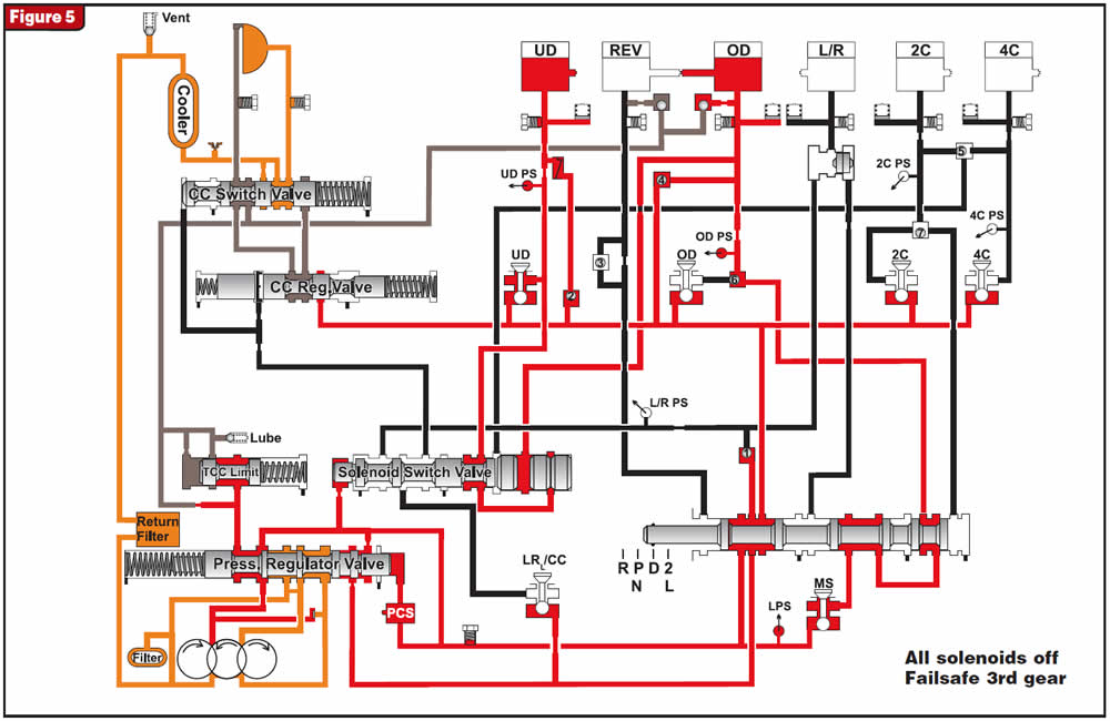
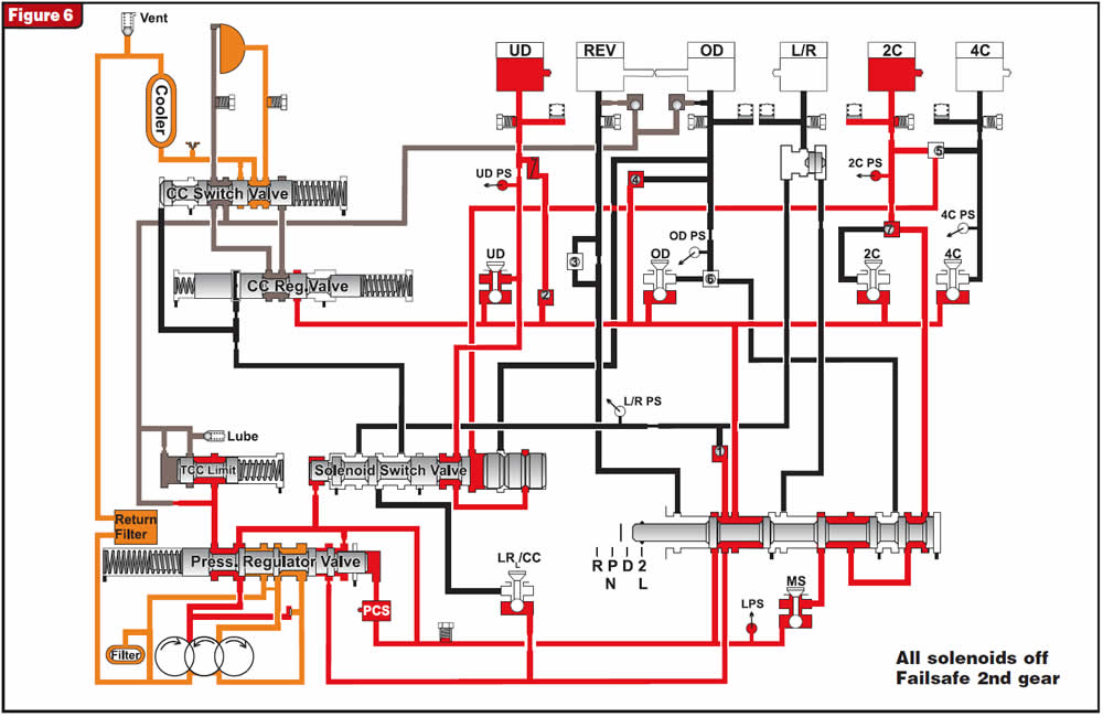
Finally, should the computer place the transmission into a no-shift failsafe mode by pulling power to the solenoids via the relay, the multi-select solenoid will provide a 3rd-gear failsafe in the D range by applying the overdrive clutch and 2nd-gear failsafe in the Manual 1 or 2 range by applying the second clutch (see figures 5 and 6).
By understanding the function and operation of this multi-select solenoid, one could easily determine the negative affects should this solenoid fail mechanically in either the energized or de-energized position.
If it were to stick in the energized position, a no-reverse condition would occur along with a neutral shift into 3rd. The computer would then failsafe to 3rd but, since 3rd or 4th could not be obtained, the vehicle would not move until the key was cycled. Sounds similar to what happened in the 41TE when the sun-gear hub would snap.
If it were to stick in the de-energized position, the transmission would have reverse but when Drive was selected it would have a bind-up feeling as the UD, L/R and OD clutches would all be on at the same time. If you pushed hard into the throttle to force a movement so that the output-shaft-speed signal exceeded 150 rpm, the computer would command the L/R clutches off, placing the transmission into 3rd as the failed multi-select solenoid would be keeping the OD clutches on. And for the same reason, it would bind up again when the computer commanded an upshift into second. Should the computer pick up a gear-ratio problem it would failsafe to 3rd, and the unit would have 3rd if the OD clutches were not wasted by that time.
So with the multi-select solenoid having various functions, it also can cause various problems if it malfunctions.


