
Technically Speaking
- Author: Wayne Colonna, Technical Editor
Finding the cause of an electrical problem on a Ford Expedition requires some detective work
A 2002 Ford Expedition equipped with a 4.6-liter V-8 and 4R70W transmission came into the shop with a host of solenoid electrical codes.
A visual inspection of the vehicle harness plugging into the transmission case connector did not reveal any concerns there. So the decision was made to drop the pan and inspect the hard-wire frame and solenoid connections. A resistance check of all the solenoids showed the correct readings.
But since the pan was down, the technician installed a new set of solenoids, reinstalled the pan, put in fresh fluid and cleared the codes. When the vehicle was driven it had only second gear, and many of the codes came back.
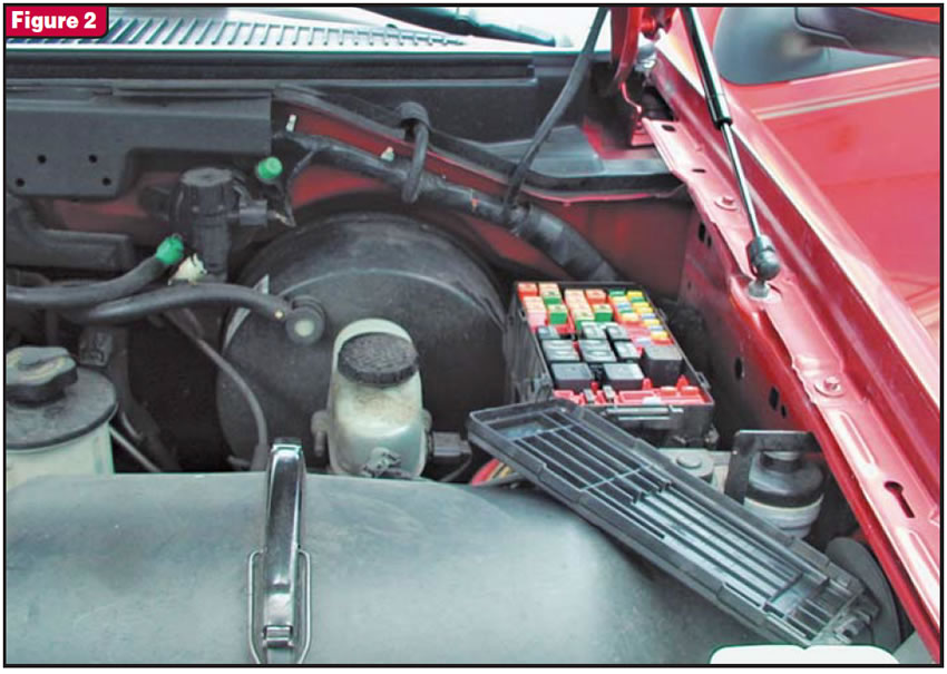
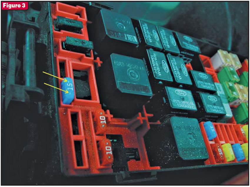
At this point the shop obtained a wiring diagram similar to the one shown in Figure 1. Instantly the technician saw that fuse 23 supplied power to the solenoids in the battery junction box on the left side of the engine compartment (see Figure 2). The technician then located the No. 23 (15-amp) fuse (see Figure 3). Instead of pulling the fuse, he used a voltmeter with the negative lead placed to ground. With the positive lead he quickly checked for voltage across the back of the fuse’s test points (identified by the arrows in Figure 3) and found full battery voltage on both legs of the fuse.
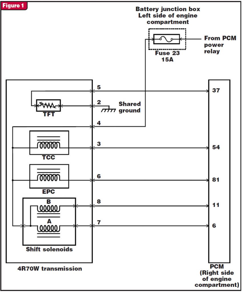
This confirmed in the technician’s mind that the PCM power relay was working with the ignition switch and that power was passing through the fuse to the transmission. Since the PCM was inside the engine compartment, the technician decided to see whether there was voltage on the ground side of each of the solenoids with the engine off and ignition on. Starting with terminal 6 for shift solenoid A, he found no voltage. He then checked terminal 11 for shift solenoid B and terminals 54 and 81. All read 0 volts.
The technician thought to himself: “Does this mean that all these wires are cut somewhere? After all, the fuse is good.” So he decided to make continuity checks from the case connector to the PCM on each of these ground wires, and they all checked OK. Finally, the technician decided to check for voltage at terminal 4 in the connector that plugs into the transmission and found 0 volts.
Now he knew there was a problem between the fuse and the transmission. Surely this wire was broken. So he quickly pulled out the fuse with a pair of needle-nose pliers and set it aside, and with the ignition still on he checked to see which side of the fuse cavity had the voltage supply from the PCM power relay. Once he identified this circuit, he knew that the opposite leg of the fuse cavity would be the circuit to be tested. So he turned off the ignition and checked that circuit for continuity to the transmission, expecting to see an open circuit, but he did not. Instead, he had great continuity. He thought to himself: “This circuit couldn’t have been shorted to ground; otherwise, the fuse would have blown. So what’s the deal?”
Now second-guessing himself, the technician went back to the fuse to recheck it. Once he picked it up with his hand he immediately saw what had happened. The fuse leg on the circuit to the transmission was burned away. The fuse was not blown, and although power was passing through the fuse it did not continue to the transmission, as that fuse leg was burned significantly enough to lose complete contact.
The root cause of this problem was that the contact of the fuse leg was loose enough to allow voltage to arc from the leg to the contact. Over time, the arcing caused the fuse leg to burn away, which explains why the fuse didn’t blow. Obviously, a new fuse would need to be installed, but the real fix was to carefully squeeze together the fuse-leg contact for a tighter fit so that the problem would not be repeated.

That is one more for the “Arc-ives.”


