Technically Speaking
- Subject: Common wear-out areas in the valve body
- Unit: U140/240 series
- Vehicle Applications: Toyota, Lexus
- Essential Reading: Rebuilder, Diagnostician
- Author: Wayne Colonna, ATSG, Transmission Digest Technical Editor
Continuing this month with the information provided by Jim Dial on the U-series 140/240 transmission we cover some common wear-out areas in the valve body that can cause this unit to fail again prematurely. The best thing about this is that they are all sleeves and are easily repaired. These items were discovered as the U140/U240 Technicians Diagnostic Guide was being written.
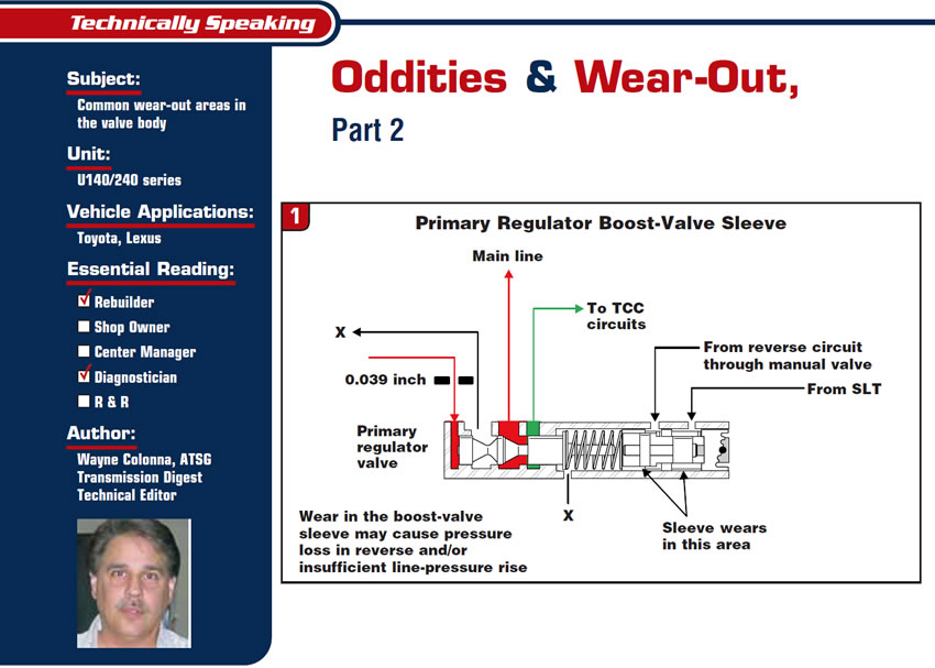
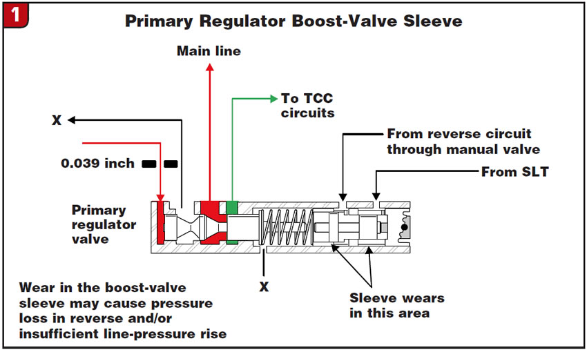
First up is the primary regulator-boost-valve sleeve. Figure 1 shows a cross-sectional view of this sleeve and its wear points. Wear in these areas can cause insufficient pressure rise in both drive and reverse. Figure 2 shows a close-up of this sleeve in the reverse boost area. A simple way to check the sleeve in this area is to put the boost valve into the sleeve backward, and when you get close to the worn area the valve will have some serious flop from side to side.
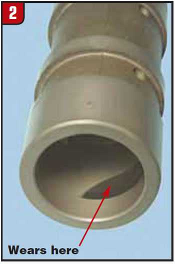
Referring back to Figure 1 for a second, notice that there is an exhaust port up by the primary regulator valve that will create a nice drain for reverse boost oil – not good. Also, one other note: The end of the boost-valve sleeve is stepped where the roll pin goes through, which means it’s adjustable. The valve bodies that I have had my hands on have had the roll pin in the center of the adjustment range (see Figure 3).
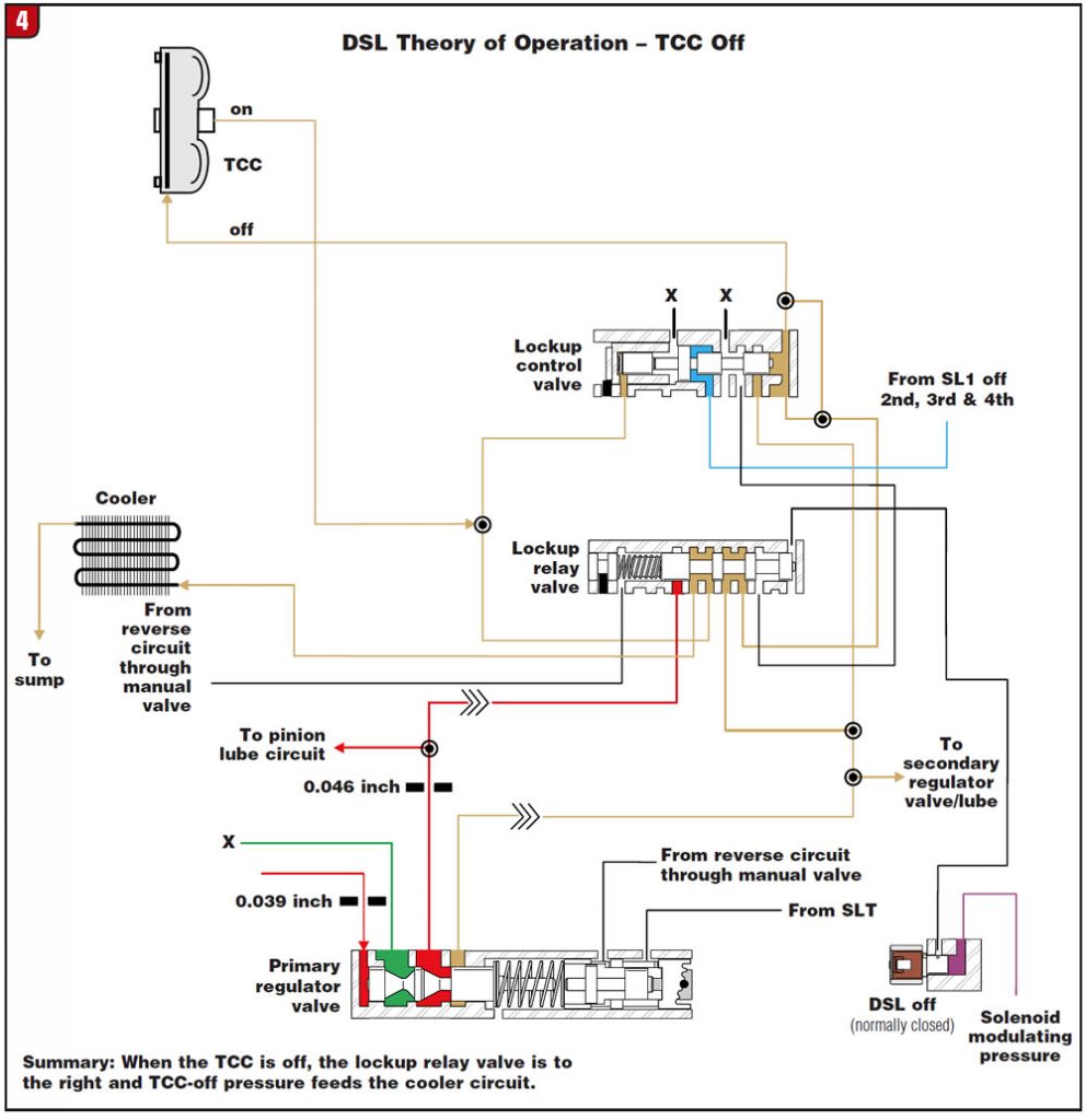
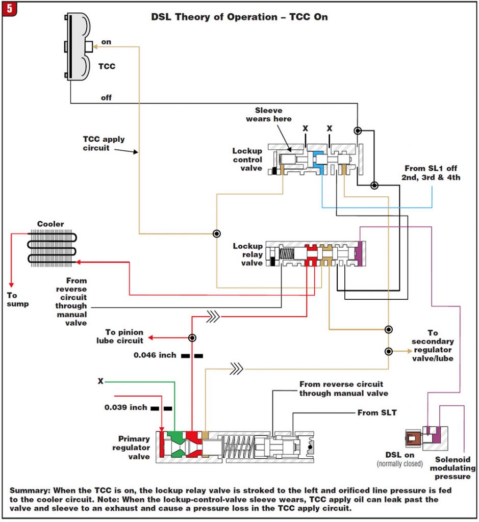
Second in line is the lockup-control-valve sleeve. Figure 4 shows a cross-sectional view of this valve, the plunger and its sleeve. Wear in this area can cause a pressure loss in the torque-converter-clutch apply circuit. Figure 4 shows a partial hydraulic schematic of the TCC when it’s released. Figure 5 shows a partial hydraulic schematic of the TCC when it is applied; notice that right in front of the sleeve there is an exhaust that will create a nice drain for the TCC apply circuit – again, not good. A simple way to check the sleeve is to take the lockup control valve and install it into the sleeve and check for wobble or “flop” as we did previously. Note: The small plunger that fits in the sleeve is the same diameter as the first land of the lockup control valve.
Third in line is the clutch-apply control-valve sleeve. Figure 6 shows a cross-sectional view of this valve and the plunger and sleeve. Figure 6 also shows the numerous hydraulic circuits that are directed to this valve. Notice the plunger and sleeve at the end of the clutch-apply control valve; of course, the sleeve is the wear item in that lineup. This can cause a pressure loss in the forward ranges or a condition affecting movement of the valve, as the small plunger can get hung up in the sleeve – which is, of course, for the third time, not good.
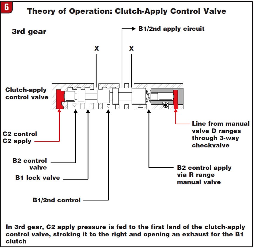
The complaints related to problems with this sleeve may be numerous. As you can see, there are many circuits going through this valve, and its main function is to sequence clutch-apply and clutch-release circuits. For an example, refer to Figure 6. In third gear there is C2 apply pressure on the first land of the clutch-apply control valve stroking the valve to the right. This opens up a port to connect the B1/2nd apply circuit to an exhaust. If the port were not open the result would be a severe bind on the shift.
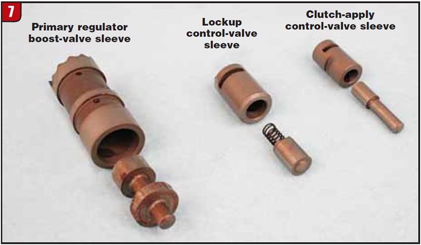
This sleeve also is very simple to check; all you have to do is install the plunger into the sleeve and see whether there is wobble or “flop” as we have done in all the previous checks. One more thing: The sleeve in this area has not been worn as badly as the others have been, but why not check it while we have this valve body apart? See Figure 7 for a view of all three sleeves.
These parts are available through your local Toyota dealer, but there have been some complaints of back orders, as there have been some problems keeping them in stock. Sonnax is getting really close to having all these sleeves available as well. The part numbers follow:
- Main regulator boost-valve sleeve RAV4 (Toyota part number) 35417-28030
- Main regulator boost-valve sleeve Camry (Toyota part number) 35417-21010
- Main regulator boost valve and sleeve (Sonnax) 57917E-01K
- Clutch-apply control-valve sleeve (Toyota part number) 35492-21010
- TCC control-valve sleeve (Toyota part number) 35211-21010
One thing for sure – as we talked about in last month’s article, it would be very difficult to find problems in a valve body like this unless you had an oil-circuit diagram to know how it worked. After all, how can we fix something if we don’t know how it works?
I hope this information will be helpful, and Jim and I hope to see you in the next few months on the road as we finish up our 2008 seminar season.


