


A Ford vehicle equipped with a 4F27E transmission has a “no reverse” condition after overhaul.

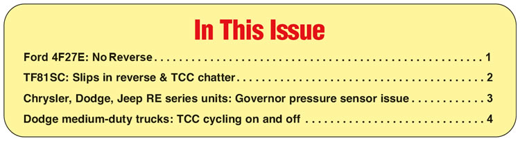
The incorrect reverse piston was installed into the reverse drum, which resulted in excessive clutch clearance, making it unable to reach zero clearance (figures 1 and 2).
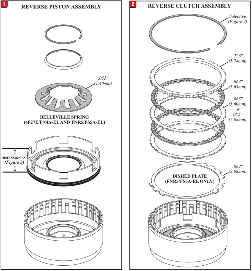

Mazda vehicles equipped with the FN4A-EL transmission use a reverse piston that is 1.375” (34.925mm) tall.
Ford vehicles equipped with the 4F27E transmission use a reverse piston that measures 1.455” (36.957 mm) tall (Figure 3).
NOTES: Both Ford and Mazda vehicles equipped with the FNR5 or FS5A-EL use the 1.455” (36.957 mm) reverse piston.
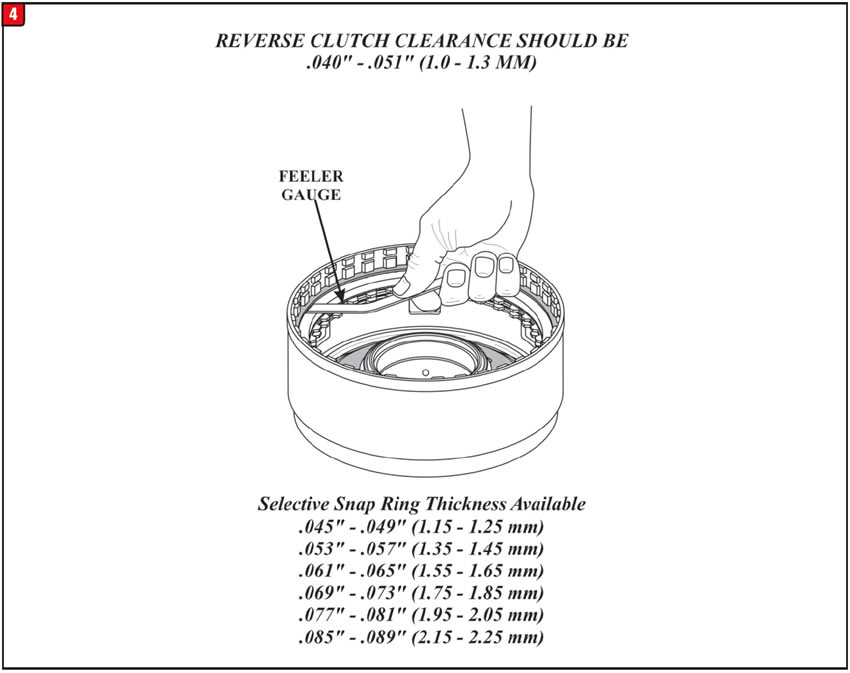
Reverse clutch steel plates come in 0.063” (1.60mm) or 0.082” (2.08 mm) thicknesses. The clutch pack retaining snap ring is used to set final clutch clearance as shown in Figure 4.
The top pressure plate used by both the 4F27E/FN4A-EL and the FNR5/FS5A-EL is 0.226” (5.74 mm) thick.
The reverse frictions used by both the 4F27E/FN4A-EL and the FNR5/FS4A-EL is 0.064” (1.63 mm) thick.
The Belleville Spring used by both the 4F27E/FN4A-EL and the FNR5/FS4A-EL is 0.055” (1.40 mm) thick and has 12 fingers.
Only the FNR5/FS5A-EL uses a .082” (2.08 mm) thick dished plate at the bottom of the reverse clutch pack.
Added Tech:
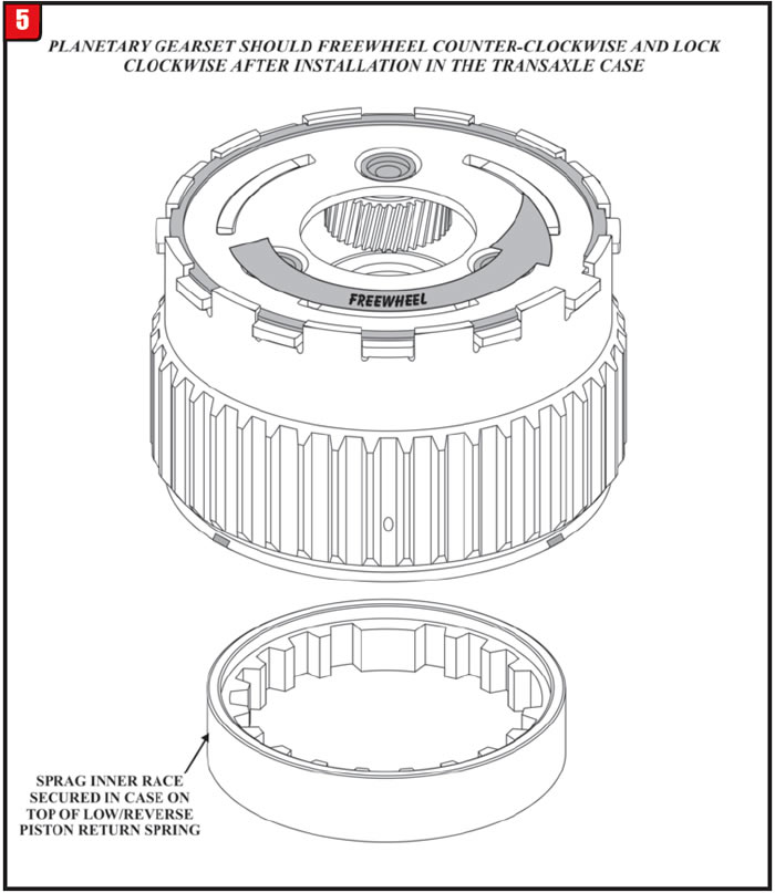
See Figure 5 for the correct low one-way clutch assembly used in both the 4 and 5 speed units.
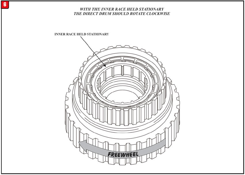
See Figure 6 for the correct reduction one-way clutch assembly used in all 5 speed units.


A vehicle equipped with the TF81SC transmission may have a complaint after overhaul of a delayed or slip in reverse. A secondary complaint may be a converter clutch chatter or engine rpm drop. Other complaints may also be harsh shifts and a bind-up sensation.
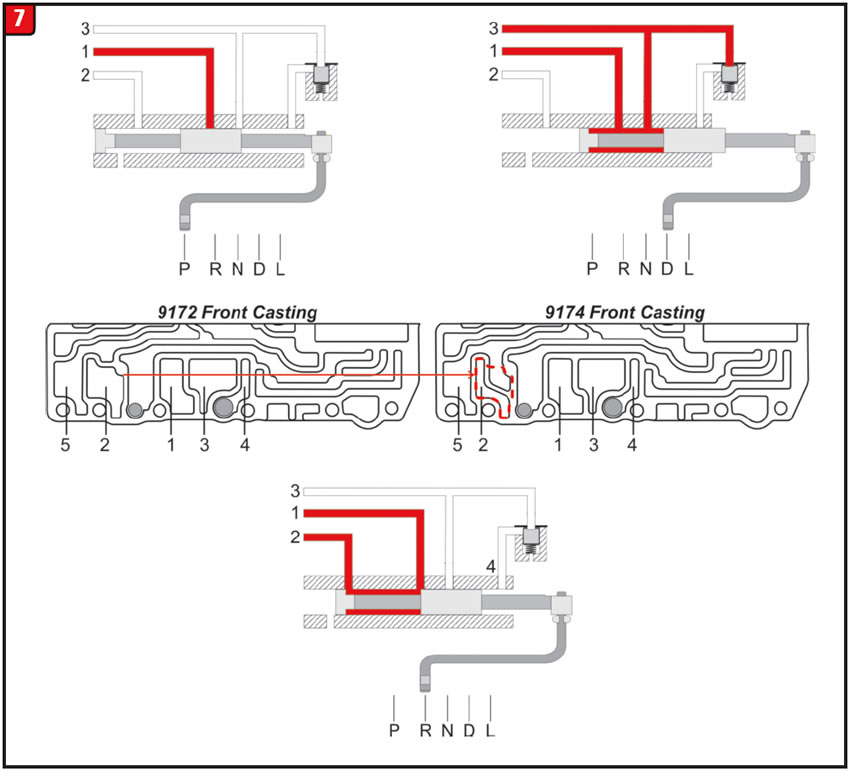
1) Installing the 9172 gasket on the 9174 valve body (See Figure 7):
In reverse: Reverse chatter or slip due to loss of boost pressure. Stall the engine or loss of engine rpm to converter clutch apply.
In drive: High line pressure due to cross-leak into reverse boost circuit harsh and/or bump shifts with a bind-up sensation.
2) Installing the 9174 gasket on the 9172 valve body: No functional problems. However, if the original bonded gaskets are removed and replaced with after-market gaskets, due to a part of the gasket being unsupported, a piece can break off and become lodged in the reverse boost valve which could cause engagement problems (See Figure 8).
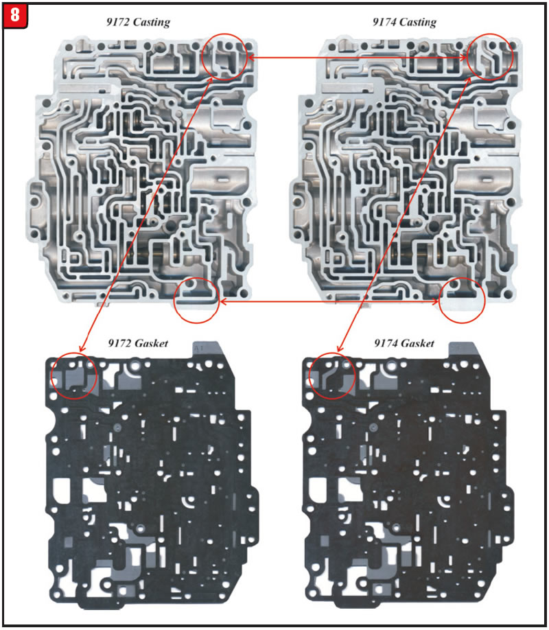
Install the correct gasket onto the correct valve body casting or reuse the bonded plate and gaskets if they are in good condition.


A 2005 Dodge 2500 4×4 with a 5.9L diesel using the 48RE transmission comes into the shop to be rebuilt. A new governor pressure transducer (sensor) was installed as part of the rebuild. The initial test drive after overhaul was perfect for approximately 5 miles before code P0868 set for governor pressure transducer volts being too high. A new transducer was installed eliminating the code, but it went several miles before setting P0868 once again.
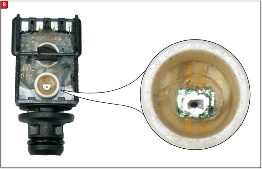
One cause may be new defective transducers. Governor pressure enters the transducer, which it uses to provide a linear voltage signal to the computer based on pressure. Generally, the transducer will provide an approximate 0.5 volts when zero psi of pressure is present inside of it. As pressure increases the voltage increases as well. Approximately 3.5 volts will be observed at maximum governor pressure. It is in the area where pressures are converted to voltage that the pressure build up is blowing a hole inside the transducer (Figure 9). This problem is more prevalent with performance transmissions, which run higher line pressures.
BD Diesel Performance produces a pressure transducer upgrade kit that replaces the plastic transducer with a more reliable and durable metal unit.

Complete kit, #1060602. BD Diesel Performance: www.thoroughbreddiesel.com

A Dodge pickup is brought in with a complaint of intermittent and erratic bumps that seem to clear up once the vehicle has reached 60 mph or greater. The technician driving the vehicle notices that the converter clutch is being commanded on and off when the bumps are felt. The way the converter clutch was being commanded on and off was not occurring in the typical fashion these vehicles are notorious for. Usually, the shuttle is more rhythmic between 45-50 mph. The converter clutch in this case was more
“out/off” then quickly back “in/on” maybe once or twice then stop before intermittently repeating itself.
When it comes to TCC shuttle, vehicles using the RE transmission (42, 44, 46, 47 and 48), there is a healthy list of possibilities which can vary depending on it being equipped with a gas, 12 valve or 24 valve diesel engine. The vehicle cited here was a 2001 Dodge 2500 5.9L diesel with a 47RE transmission. The customer mentioned that this problem began immediately after an engine oil change. The tech decided to do look around where the filter was. He saw that the A/C high pressure switch was located on the discharge line near the compressor as well as being close to the filter. He unplugged it and noticed oil was in the connector. He drove the vehicle with the pressure switch unplugged and the complaint was no longer evident.
In this case the connector was cleaned to remedy the complaint, as the switch was still functional.
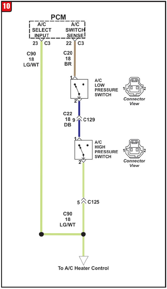
Note: The A/C high-pressure switch is connected in series electrically with the low pressure switch and the heater control, between ground and the PCM (Figure 10). This means the low-pressure switch (mounted on the top of the accumulator) could also become suspect. Unplugging one or the other of these switches is a quick test to see if it corrects a TCC shuttle condition. If it does, each switch will need to be tested to know which one has failed and will need to be replaced.
Low pressure switch diagnosis:
- Disconnect and isolate the battery negative cable.
- Unplug the A/C low-pressure switch wire harness connector from the switch on the accumulator fitting.
- Install a jumper wire between the two cavities of the A/C low-pressure switch wire harness connector.
- Connect a manifold gauge set to the refrigerant system service ports.
- Connect the battery negative cable.
- Place the A/C heater mode control switch knob in any A/C position and start the engine.
- Check for continuity between the two terminals of the low pressure cycling clutch switch. There should be continuity with a suction pressure reading of 296 kPa (43 psi) or above, and no continuity with a suction pressure reading of 172 kPa (25 psi) or below. If OK, test and repair the A/C switch sense circuit as required. If not OK, replace the faulty switch.
High pressure switch diagnosis:
- Disconnect and isolate the battery negative cable.
- Unplug the A/C high pressure switch wire harness connector from the switch on the refrigerant system fitting.
- On the four terminal high-pressure switch, check for continuity between terminals C and D. On the two terminal switch, check for continuity between both ter-minals of the A/C high-pressure switch. There should be continuity. If OK, test and repair the A/C switch sense circuit as required. If not OK, replace the faulty switch.

October 2018 Issue
Volume 35, No. 10
- Ford 4F27E: No reverse
- TF81SC: Slips in reverse & TCC chatter
- Chrysler / Dodge / Jeep RE series units – PO868: Governor pressure sensor volts to high
- Dodge medium-duty trucks: TCC cycling on and off


