

For some time now, vehicle manufacturers have been scrambling to develop the best mousetrap in order to propel their vehicles down the road. Improvements with engine performance have been ongoing with a number of enhancements that has reduced emissions and improved output, some more costly than others. The situation with transmissions has been even more chaotic.
Beyond the ongoing increase with the amount of gears that are being crammed into transmissions today is the issue of basic architecture. Although the traditional step-type automatic transmission is still the predominant platform used by vehicle and transmission manufacturers, other designs have been making slow and steady inroads into the vehicle population. A CVT transmission, once thought to be an isolated occurrence, has become somewhat mainstream, not only globally but in the USA as well. What started in Europe over a decade ago is also showing up in increasing numbers here in the states, which is the dual clutch transmission.
A DCT is produced in two basic forms, a wet DCT or a dry DCT (DDCT) in order to accommodate a wide variety of vehicle requirements. A DDCT is primarily used for lighter vehicles with smaller engines whereas a DCT is normally reserved for a heavier, more upscale vehicle with a larger engine. The bulk of either transmission platform production has been used in vehicles that are transverse front-wheel drive.
Although several manufacturers of transmissions or transmission components have been jockeying for position on the DCT field, VW was certainly one company that took the lead early on with the launch of the DSG (02E) in 2003. Currently, the 02E is one of the most plentiful DCT models on the road today and not just in Europe.
When Audi decided it was time to develop an inline DCT, they started with a clean sheet of paper and along with BorgWarner launched the 0B5 in late 2008. The 0B5 has little in common with the 02E. The 0B5 is an AWD longitudinal wet DCT that is used in a variety of different Audi vehicle models and can accommodate various engine sizes. As with other transmission families, there are variations of the 0B5 based upon vehicle need, externally and internally. The other 0B5 handles are DL501 and S-Tronic.
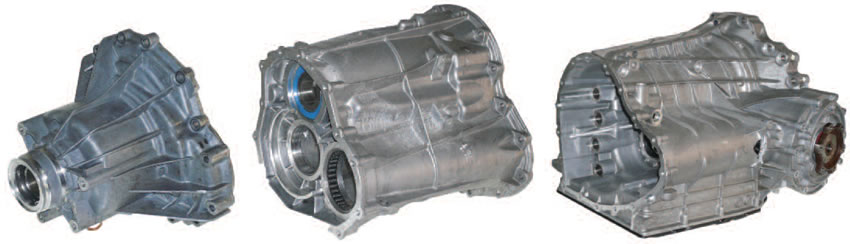
The Audi DCT rivals most automatic transmissions in stature due to the fact that it is a monster weighing in at over 300 pounds. It’s so long that it’s tough to capture in one view and better shown in a panel, as on the cover here. The main case section primarily houses the dual clutch assembly, differential and supports the front end of the gearing. The middle housing is where most of the gears and shafts are located, along with the synchronizer shift forks. The extension housing, once removed, gains access to the output gears and Torsen (torque sensing) center differential as well as other components. Audi recommends a sizable holding fixture and engine hoist along with different clamping tools when doing a major repair on this transmission due to the weight; however, the unit can be serviced with a little ingenuity.
To avoid shift shock Audi instituted a particular computer strategy that reduces engine torque at the time at which a shift occurs. When doing diagnosis, ensure that the scanner is compatible to the computer program and when any repairs are made, carry out all computer relearn and shift adapt procedures to avoid drivability or durability issues. The 0B5 does have a substantial amount of electrical components to deal with and the valve body is a mechatronic design.
Unlike other DCT models the 0B5 actually has two different fluid systems to contend with. There are two separate vents on the top of the case and two different fill/level check plugs on the side. The dual clutch assembly portion of the transmission takes a specific type of ATF; whereas the gear and differential sections of the transmission use a hypoid type of oil. Always use the proper brands of oil and ensure that the transmission is at the correct temperature before checking oil levels.
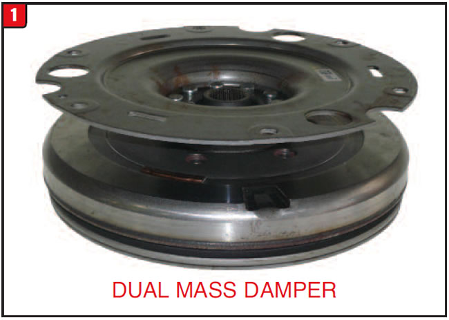
Flywheel assembly:
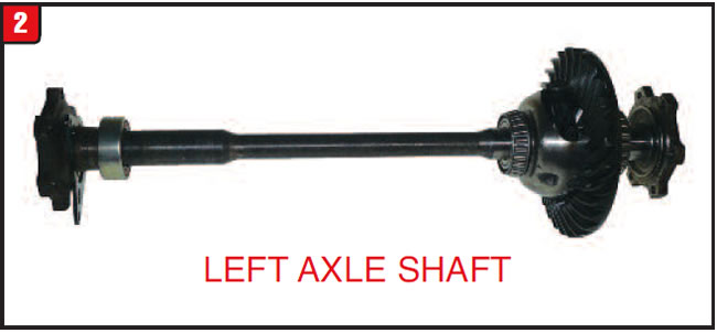
With the transmission out of the vehicle, the first item to be removed is the flywheel assembly (Figure 1). The flywheel is actually a dual-mass design damper assembly and is the main connection between the engine and transmission. A DCT does not use a torque converter or clutch as in a manual shift transmission. Before the flywheel can be removed, however, the left-side axle shaft must be removed because the shaft actually goes between the flywheel components. The left-side axle shaft is held in place with a bolt-on support plate. With the axle shaft removed, the flywheel assembly will slide out, exposing the stub input shaft.
Front differential:
The front differential section of the transmission is fairly straightforward and comparable to other in-line applications. The differential is a ring gear/pinion gear design and is held into the main case housing with a side cover (Figure 2). Unlike the left-side axle shaft, the right-side axle stub is held in place with a clip that should be replaced during any repair. The entire transmission must be disassembled to gain access to the pinion gear, which is held in place with a snap ring.
Dual clutch assembly:
With the flywheel out of the way, the front cover is visible and contains the bearing and metal-clad seal for the stub input shaft. Directly behind the cover is the main component that defines a DCT, which is the dual clutch assembly. Audi recommends removing the cover and dual clutch assembly together vertically with a hoist, although it’s not quite that bad. The cover is bolted in and contains a large O-ring that compresses between the cover and case. There is a snap ring behind the front metal-clad seal that retains the cover to the clutch assembly.
The dual clutch assembly is a compact unit that contains the K1 and K2 clutch packs and related components (Figure 3A). The assembly is held together by a large snap ring that retains the input flange to the steel housing and there are four sealing rings that are used for clutch apply. Once the input flange is removed, most of the components are accessible.
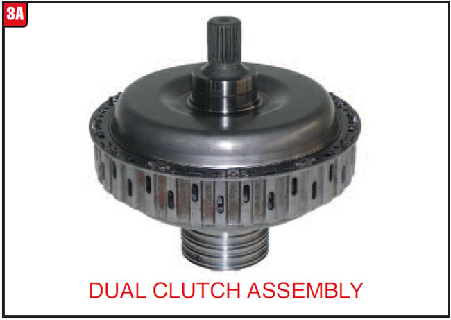
The K1 clutch pack is the larger of the two and is responsible for 1st, 3rd, 5th and 7th gears, whereas the smaller diameter K2 clutch pack is applied in 2nd, 4th, 6th and reverse gears. The K1 clutch hub is splined to be solid input shaft and the K2 clutch hub is splined to the hollow input shaft (Figure 3B). The pump drive gear presses onto the sealing ring support.

Although the bonded rubber piston for the K2 clutch pack is accessible, that is not the case for the K1 clutch apply piston. As with the 02E dual clutch assembly, Audi chose to weld sections of the clutch housing together, thus preventing replacement of the K1 piston. If the K1 frictions show signs of slippage or the clutch pack does not air check correctly, the housing assembly will have to be replaced. The K1 clutch pack consists of five frictions and five steels, whereas the K2 clutch pack has six frictions, five steels and two cushion springs.
Pump assembly:
In order to provide pressure, manufacturers have used an array of different pump configurations over the years, both direct drive and remote axis designs. The 0B5 however stands alone in how it operates. The pump is directly behind the dual clutch assembly and contains the sealing ring bore for the dual clutch housing. Although the pump can be unbolted from the front, the pan, filter and valve body must be removed to get the pump out of the case.
The 0B5 pump is a gear-driven, remote-axis design with external toothed gears to provide apply and control pressures within the transmission. What makes this design unique is the addition of what Audi calls a suction jet pump that bolts to the main pump (Figure 4). The suction jet pump is merely a long plastic tube that extends from the sump to the back of the oil pump and uses a Venturi action to draw fluid up into the cooling oil passages.
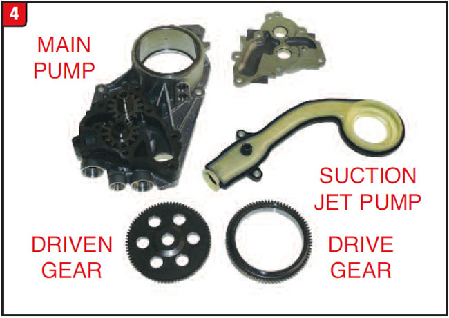
This arrangement allows for a reduction in the size of the main pump and limits the required horsepower to drive it. Passages at the bottom of the main pump connect directly to the oil apply tubes in the valve body. Note that right next to the pump assembly is a harness and electrical connector, which is for the rpm sensor assembly that must be disconnected before the case halves can be separated. The round sleeve of the connector must be rotated correctly for removal.
Center differential:
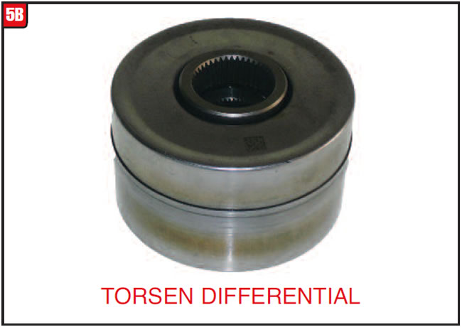
Before the case halves can be separated, items need to be removed from the back of the transmission on AWD applications, therefore the extension housing must come off. The housing has a support sleeve that may or may not come off with the housing (Figure 5A).
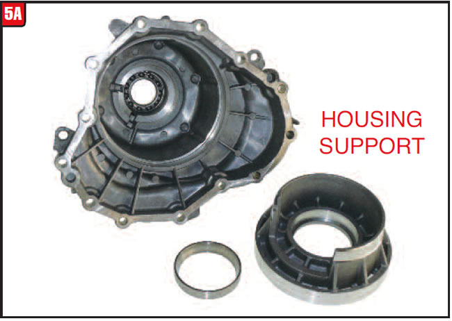
The sleeve contains the bearing race for the rear bearing of the output gear and must be removed to gain access to what Audi calls the center differential, although there are only two units in the transmission. Use caution not to cock the sleeve during removal or installation. The center differential is a Torsen design and it cannot be disassembled (Figure 5B). The center differential provides a continuous torque split of 40% to the front differential and 60% to the rear differential.
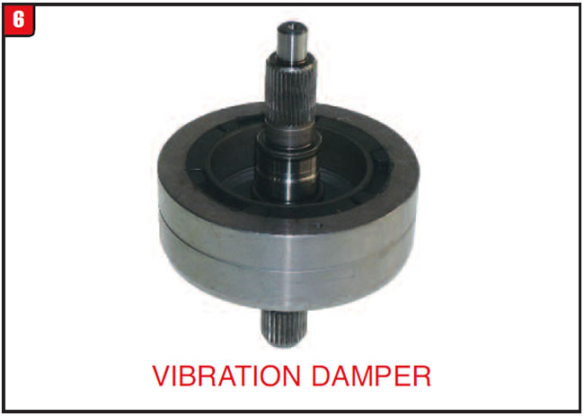
Depending on application, there may be another doodad to contend with within the extension housing. Some models may use a vibration damper that is situated between the center differential and output flange (Figure 6). The vibration damper is a single assembly with a shaft sticking out at both ends that splines to the differential and output flange. There is also a coil spring that goes between the damper and differential in order to maintain a specific load on both components.
Output gears:
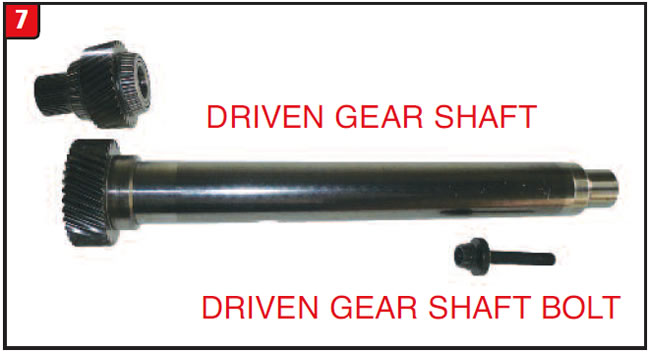
Few transmissions on the planet use an output gear arrangement like the 0B5. The drive gear (spur gear) is supported by two tapered roller bearings and splines to one part of the center differential. There is also a caged bearing that fits into the front bore. It is the driven gear that is a bit odd due to the fact that it’s about 2 feet long (Figure 7). Before the rest of the transmission can be disassembled, the driven gear 12-point bolt must be removed, which is at the other end of the shaft. The bolt attaches the long driven gear shaft to the pinion gear at the front of the transmission and of course there is a special tool needed to accomplish the task. The special tool locks the driven gear to the case so that the bolt can be removed or installed but, then again there is always an impact gun. In addition, the driven gear is actually positioned at an angle to the rest of the transmission, which is why both gears have teeth that are cut at a specific angle, unlike how regular output gears would be.


Gear train:
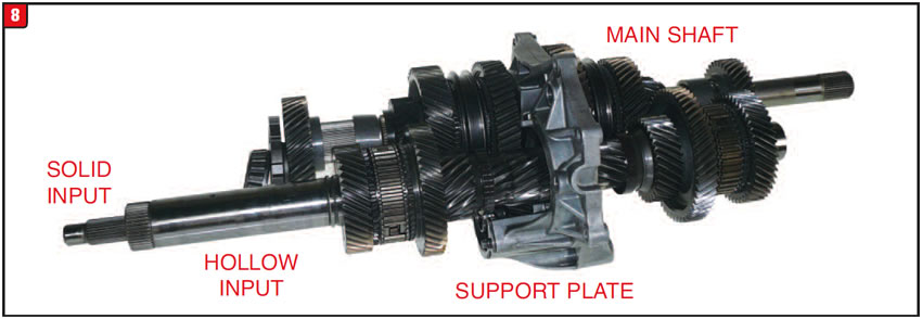
With the front end and rear end stuff out of the way, the case halves can be split apart to expose the primary gear train. The gear train is mainly housed in the intermediate section of the transmission and is held in position by a support plate that bolts to the intermediate housing. The support plate contains a ball bearing for the input shaft assembly and a tapered roller bearing for the output shaft assembly as well as the reverse idler gear. At this point, the carcass resembles a normal looking manual shift transmission with shafts, gears and synchronizers (Figure 8). The key difference between the designs is that a manual shift has one input shaft, whereas a DCT has two.
It will take some creativity to disassemble the maze of gears due to how everything is pressed together. The gear train in figure 9 was partially disassembled; however, to remove all the gears will take a variety of different pullers and a hydraulic press. Use caution; some components are held in place by a snap ring while others are not. There are four synchronizer assemblies to provide all seven forward gears and reverse, although they are not exactly the same. The two synchronizer assemblies that provide the lower gears and reverse use a three-piece synchro ring design, whereas the higher gear synchro rings are one piece design. Mark the position of the synchronizer assemblies during disassembly to avoid the hub offset being in the wrong direction during reassembly.
Both input shafts and the output shaft have fixed as well as rotating gears that make up the assemblies and have either a drive or driven function. The first input shaft to look at is the hollow-shaft design that is driven by the K2 clutch (Figure 9).
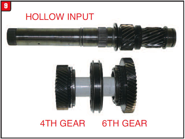
The hollow shaft is supported at the front by a straight roller bearing and at the back by a ball bearing. The two rotating gears at the front of the shaft are for 4th and 6th gears and the shaft also contains the front sensor ring for the ISS. The 4-6 synchronizer assembly is also splined to the hollow shaft.
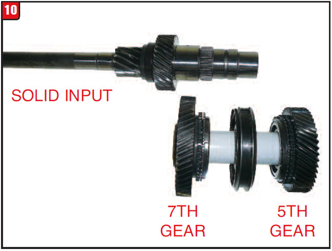
The other input shaft is a solid shaft that is driven by the K1 clutch and is just about twice as long as the hollow shaft. The solid shaft extends through the hollow shaft and is supported by caged bearings in the front and a ball bearing in the back. There is a top hat bolt that must be removed during disassembly. The two rotating gears on the solid shaft are for 7th and 5th gears and the synchronizer for those gears is splined to the shaft (Figure 10). The other ISS sensor ring is pressed onto the solid shaft and both sensor rings can be replaced and are included in certain rebuild kits as well.
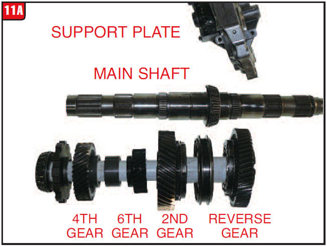
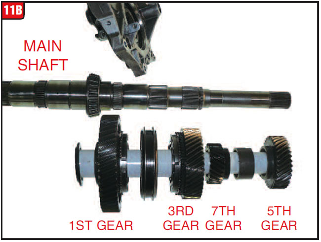
When it comes to gears the output shaft on this unit is unequaled, as in there are a bunch. The output (main) shaft is supported by a tapered roller bearing in the front and in the center of the shaft and by a caged bearing at the back that is in the bore of the output gear. As far as the gearing goes there is a chunk in front of the support plate and a chunk behind the support plate. The gears on the front side include the park gear, 4th, 6th, 2nd and reverse gears (Figure 11A).
The synchronizer assembly is for 2nd & reverse and is the three-piece ring design. The backside of the shaft includes the gears for 1st, 3rd, 7th and 5th positions (Figure 11B). Make sure that during disassembly the offset of each gear is marked to avoid reassembly grief.
Sensors and oil dams:
In conjunction with the removal of the gear train there are a couple of other items that must be addressed. The most important and sensitive component to deal with before the gear train is removed is the sensor assembly (Figure 12).
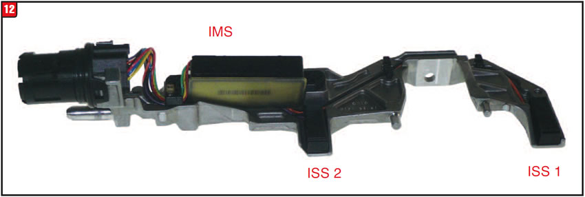
Aside from the bracket and the electrical connector and harness, there are three sensors that could be damaged by mishandling. The assembly not only contains sensors ISS 1 and ISS 2 but also contains the equivalent of an IMS (internal mode switch). The electrical connector contains an O-ring that must be replaced during repair.
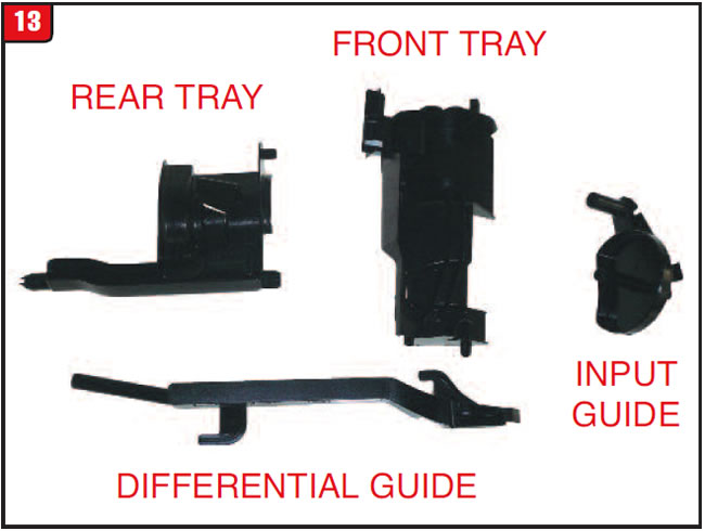
Of the four different oil dams (trays), the front oil dam is clipped to the sensor assembly and must be removed together. The other three oil dams are for the rear section, differential and input shaft, which is mounted in the extension housing area (Figure 13). All oil dams have locating pins that must be positioned correctly.
Filtration:
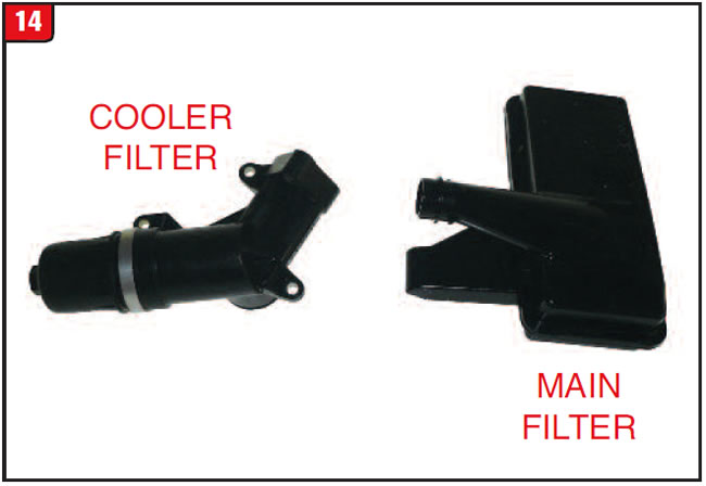
As with newer transmissions, oil filtration is not dependent upon a wire mesh (rock collector) type of filter on the 0B5. The main sump filter is a fairly elaborate and bulky type of filter (Figure 14). Depending on model, in addition to the sump filter, there may be an external cooler line filter, which can be easily replaced if needed. There is more than one type of cooler line arrangement with this unit.
Valve body:
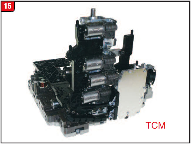
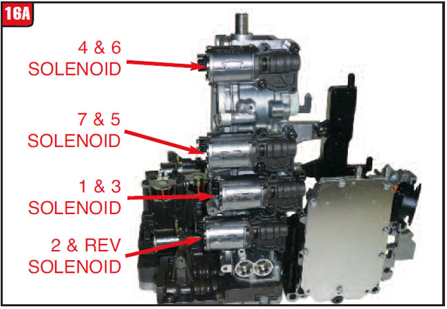
There has been countless miracles of modern science; however, few can rival the development of the 0B5 valve body assembly. Engineers responsible for this component certainly earned their stripes, although they probably do not participate in the repair business. The scope of this particular valve body is substantial (Figure 15). Beyond the fact that this is a mechatronic valve body is the issue of the overall layout and the amount of stuff that is attached to it. There are several circuit boards, connectors and sensors along with 10 solenoids and two pressure switches. The four synchronizer fork apply pistons are contained in the vertical part of the valve body and lastly, the TCM itself.
Not only does the vertical body contain the four apply pistons, but there is an individual solenoid and housing designated for each piston along with four fork position sensors, TOT and ISS 3 that is situated within what appears to be just a couple of circuit boards (Figure 16A). There are screened plates that fit between the solenoids and the vertical body. There are also two tube holes in the vertical body that connect to the cooler filter housing. It will require a little finesse to disassemble this valve body without damaging the electrical ribbons and solenoid stab locks.
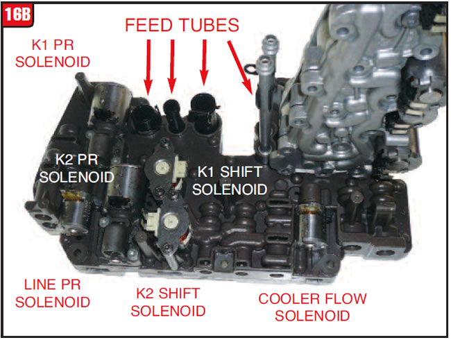
The horizontal part of the valve body is what bolts to the case and also contains several widgets to contend with. This part of the valve body not only contains six solenoids but also has holes in the casting to accommodate apply tubes that connect to the pump (Figure 16B). Although valve-body gaskets are available through the aftermarket along with a few of the solenoids and repair valves, Audi has not made a lot of tech available, so use caution when disassembling the valve body.
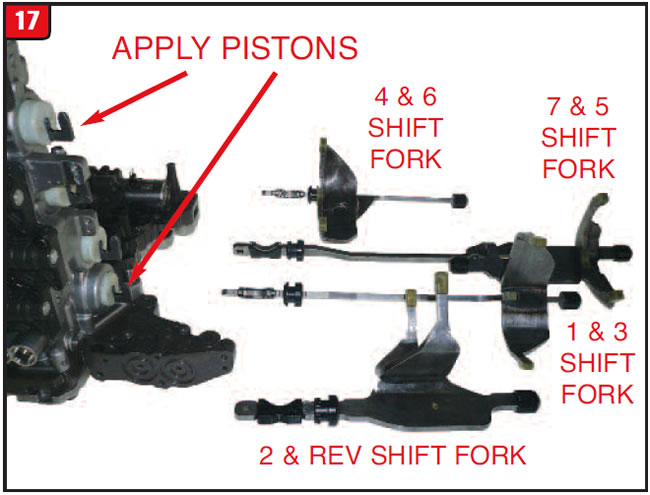
What connects the apply pistons to the synchronizers are the shift forks, all four of them. Unlike the O2E, which has small bonded pistons at each end of the forks, the 0B5 forks rely on the plastic apply pistons for movement (Figure 17). The shift forks contain permanent magnets to activate the sensors and utilize seals that ride in the bores of the case to prevent the two different fluids of the transmission from intermixing and should be replaced during a repair. When reinstalling the valve body, the hooks on all four pistons must engage the notches of all four forks.
In the end, repairing this transmission can be done, although it will take some effort and patience.
Special thanks to the folks at TransTec for supplying the transmission used in preparation for this article.


October 2016 Issue
Volume 33, No. 10
- Audi dual clutch transmission


