


A frustrated customer arrived driving a 2004 Volvo equipped with a 2.4L engine and an AW55-50SN five-speed transmission. The vehicle had 114,000 miles on it and had been bought and sold a couple of times previously. The current car owner has owned the Volvo for more than two years and was experiencing problems for almost the entire time.
The vehicle had been to another shop more than once, but to no avail, as the problem only worsened. The complaint initially was a slight hesitation going from park to drive and was erratic to boot. As time went on the hesitation grew worse, to the point of a slip, mainly after warming up. At times though, the unit worked OK.

After external items were checked out and passed inspection, the transmission was removed and disassembled to inspect the guts. Since the valve body on AW55-50SN transmissions have a high mortality rate, it was inspected first, just as a precaution. Even with 114,000 miles on it, the valve body proved to be the exception to the rule, as it checked out OK.
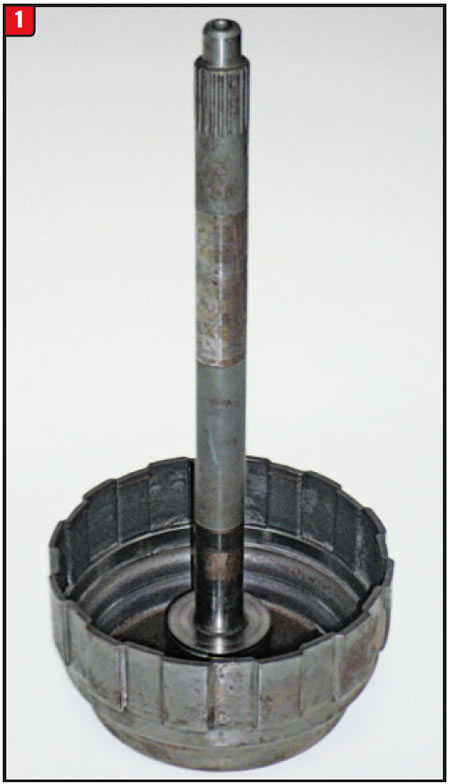
Even though the transmission had been fiddled with before, supposedly, it was taken down all the way and the focus turned to the C1/C2 clutch assembly, (Figure 1). The C1 clutch is what applies, going from park or neutral to drive. Upon disassembly, the frictions and steels were examined for signs of slippage, but considering the mileage did not look too bad. The pistons were pulled and inspected along with the drum and initially everything looked OK, but only at first glance.
The C1/C2 drum assembly was reassembled, ready to install into the case, but then a chill overtook the builder, and one more check was made. Although the C1 and C2 clutch packs air checked well, they were air checked again, this time using a modified end cover so that oil could be sprayed around the welded part of the drum and sure enough there were bubbles around the weld.
Just like other transmission types that have been plagued with cracking issues, such as the CD4E forward/direct drum or 6L80 3-5/rev drum, AW55-50SN models have also been afflicted with drum-cracking problems.

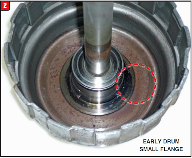
The C1/C2 clutch drum for the AW55-50SN was a carryover from the previous AW50-40LE four speeds, and although they look identical, theyʼre not. The 50-40LE drum input shaft is approximately ¼” longer than the five-speed shaft, so use caution not to intermix. The issue is where the drum is welded to the center flange, which is comparable to four and five speed models (Figure 2). As with other models, weld cracks can be really obvious or so subtle that they arenʼt even visible, as in the case of the Volvo. Many times, the only way to detect a crack is to pour solvent around one side and see if it seeps to the other side or air check the assembled drum while spraying liquid around the crack, to check for bubbles.
Beyond the difference between four- and five-speed drum assemblies are the early- and late-model five speeds. Earlier model five-speed input shafts were like four speeds, diameter wise that is, but the diameter was changed later on for increased capacity. Four-speed and early five-speed shaft diameters were 0.840, but the diameter was increased later on to 0.870. Another difference with input shafts has to do with the lube circuit. Lube holes vary depending on whether the rear planet sun gear is one piece or two. Ensure that the components are in sync.
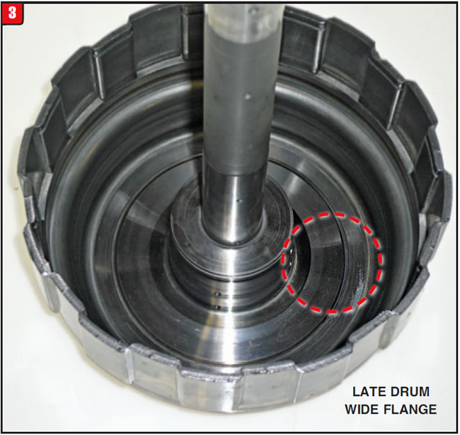
Apparently, Aisin, the 55-50SN manufacturer, decided to minimize the C1/C2 drum-cracking issue by making a modification to the drum assembly. To strengthen the weld joint, the center tower (flange) diameter was increased for capacity (Figure 3). The larger diameter weld should have a positive affect with eliminating stress cracks.
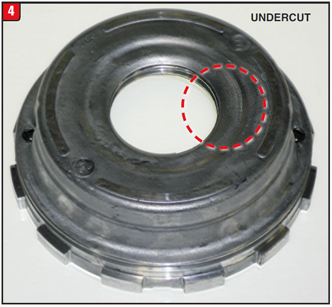
One other change to take note of has to do with the C1 clutch piston. There are two basic styles of pistons and care should be taken when choosing one. Four and five speeds primarily use a C1 piston that has a recess around the I.D. (Figure 4). Using this design is preferable.
The newer type piston does not have the same recess (Figure 5).
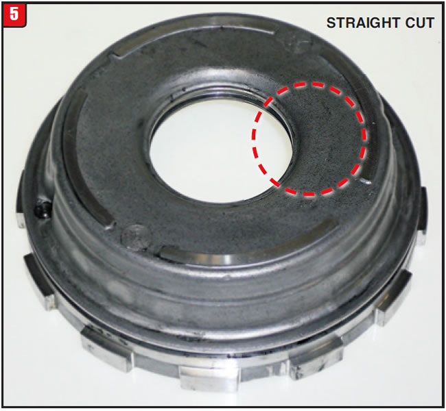
Depending on drum design, it would be recommended to modify the non-recessed piston to avoid apply oil restriction and slow engagement. Merely provide an undercut comparable to the early OE design. Beyond oil flow is stack height. Depending on drum or piston design, the piston height where the steel sets could be impacted by up to a 1/6” due to interchanging or modifying the C1 piston, therefore check clutch clearance closely.
Anytime the cause of a slip is not obvious and a welded type drum is involved, prudent judgment dictates: Scope out the welded area till it hurts.


Not all customers follow the recommended repair option, once confronted with the price tag, as in the case of the owner of a 2007 Dodge Caravan.
The vehicle was brought in due to an erratic shift condition that was getting progressively worse. The Caravan was equipped with a 3.3L engine and a new version of a 41TE (A604), called the 41TES, and it had 95,000 miles on it.
The normal diagnostic procedures were performed, such as doing the road test, and since the check engine light was on, the vehicle was driven with a scanner hooked up. A couple of codes were pulled that reflected the shifting issues and so the pan was dropped for an inside peek. With the pan off, it became obvious as to why there was an erratic shifting issue. It was due to a noticeable amount of debris that was generated by the transmission.
Based upon the condition of the pan, the unit was pulled and dismantled to see what failed and it was a mess, with worn planet-gear washers, burnt clutches and scoring of several hard parts. After the repair bill was tallied and presented to the car owner, it became apparent that plan “A” would not fly due to the bottom line. In order to save the job, a plan “B” was recommended that involved purchasing a boneyard cutout transmission as well as going soft on the R&R cost. The customer agreed, plan “B” was implemented and the unit was ordered from a local salvage yard. Once it arrived at the shop, the transmission was looked at for application purposes and then resealed and installed.
As soon as the vehicle was started, bad things happened. The check engine light came on and the initial garage shifts were a bit abrupt. A poor start to plan “B.”
After the basics were checked, a scanner was hooked up again to see what was up. There were a couple of codes that were not there previously with the old transmission. Code P0869 and code P1745 listed refer to a line pressure problem, not normal for a 41TE, but possible for the 41TES.
After further testing it was decided to pull the pan and valve body to see where the fault lay. As soon as the valve body was pulled it became obvious as to the problem, it was incorrect for the vehicle.
When launched in 1989, the A604 was state-of-the-art, utilizing adaptive learn computer strategy, which meant that the computer could monitor shift times and adjust to driver characteristics as well as clutch pack wear. Although the A604 had issues, the strategy did work and the computer would change shift parameters by using CVI (clutch volume index) readings. This was done by controlling the specific clutch pack solenoid directly, no line pressure control.
After a decade and a half, Chrysler decided that a change was needed and redesigned the system by adding a line pressure control solenoid and transducer (sensor). The first unit to receive the VLP
(variable line pressure) solenoid was the 42RLE in 2006. The name change was pretty basic, 42RLE VLP. Front wheel drive vehicles started to receive the upgrade in 2007, with some models being a phase in.
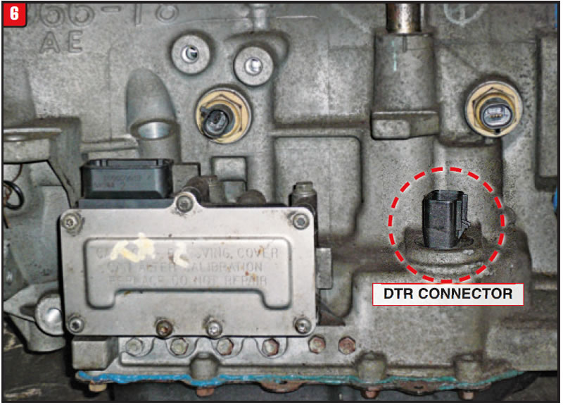
Externally, the A604 family has certainly changed, with the park/neutral layout being a predominant one. In 1996, the 41TE was upgraded to a single In MLPS/DTR connector (Figure 6).
From 1996 to 2006 there were only two harness connectors to deal with, the MLPS and shift solenoid block. That all changed with the 41TES and 42RLE VLP. There are now three electrical connectors sticking out in which to plug stuff (Figure 7).
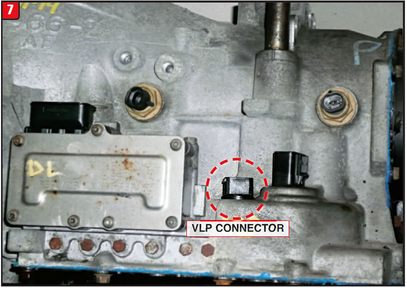
The actual line pressure solenoid and pressure transducer are two separate parts, which somewhat mimic the 62TE, but do not interchange with the six speed (Figure 8).
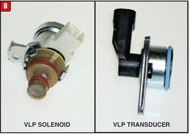
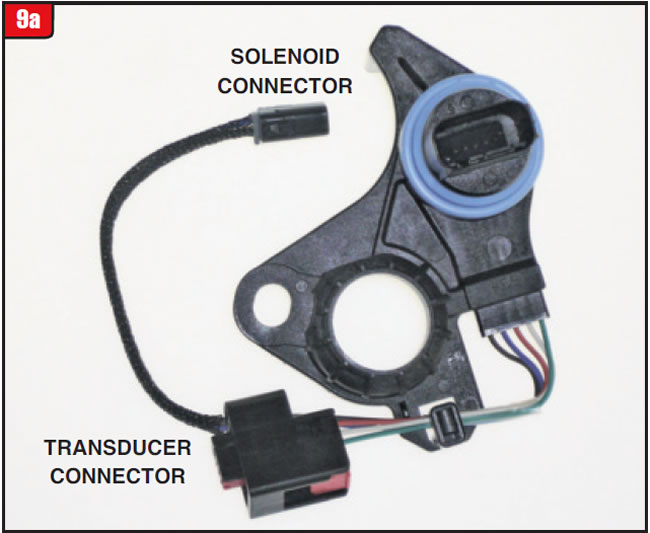
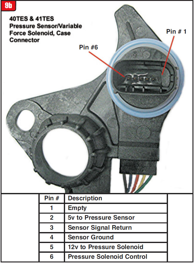
The solenoid has two connector pins, whereas the transducer has three and both require O-rings. The solenoid/transducer harness and case connector is a fairly compact component, with Chrysler doing a great job of adapting it to the existing valve body/DTR configuration. The assembly fits over the shifter shaft, like the DTR and sets on top of the DTR using the same hold down bolt (Figure 9a/9b). The harness assembly has five wires, two for the solenoid and three for the sensor. The wire positions are indicated in the illustration.
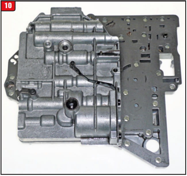
Due to computer strategy, there were not a lot of valves in the A604 and the valve body was pretty basic. On the top side, there was only one case seal and the hole for the shifter shaft (Figure 10).
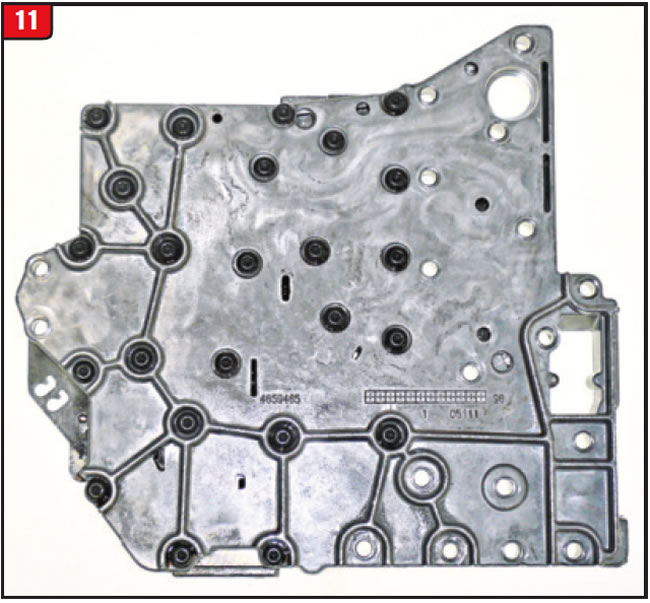
The channel plate, where the filter connects, is also fairly basic and does not contain any valves (Figure 11). There have been subtle worm track changes though, so avoid mismatching the halves.
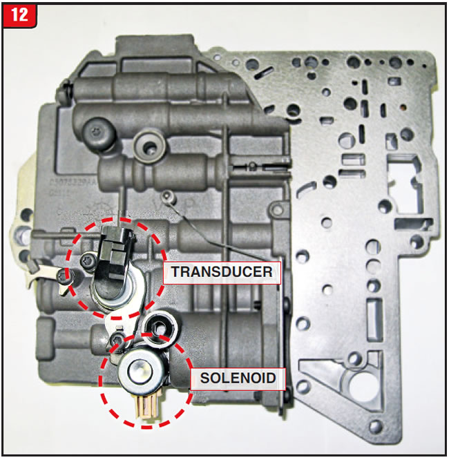
To accommodate the VLP solenoid and pressure transducer, Chrysler did a little tweaking of the housings to make room (Figure 12).
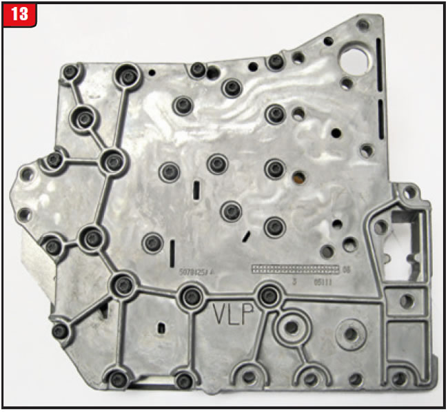
Both the solenoid and sensor are connected to line pressure with the solenoid feeding control oil to the pressure-regulator valve. Bless their hearts, Chrysler even cast in the letters VLP to identify the newer body. Even the channel plate has VLP cast into it to avoid confusion, so there is no excuse to mix up parts (Figure 13).
The issue with the Caravan cutout transmission replacement was that the case was a VLP, along with the case connector, but with a non-VLP valve body. When making a unit change, especially on 2007 vehicles, ensure that everything (the transmission, valve body and TCM) is in sync. A scanner can detect that the vehicle is utilizing desired and actual line pressure PIDʼs and that everything is functioning correctly, so that assumptions are not made.


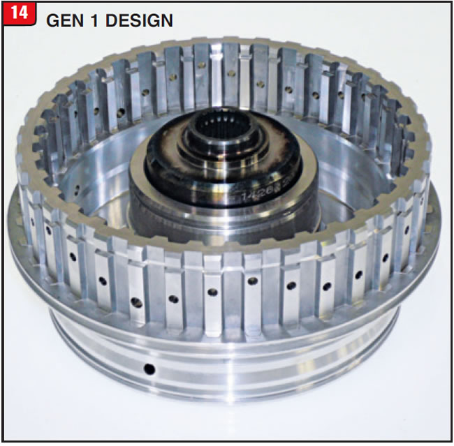
The 6T40 six-speed FWD, smaller brother to the 6T70, was released in 2008 in a variety of vehicle models and like the 6T70 has had its share of issues and upgrades. One of the main problems that has plagued both levels of GM transmissions has been breakage of the clutch cushion spring, primarily the 3-5/Rev spring. In the case of the 6T40, there have been other concerns beyond the spring breakage relating to the rotating clutch assembly. The rotating clutch contains the 4-5-6 and 3-5/Rev clutch packs, but unlike the 6T70 the input shaft splines into the drum, which is held in by a small snap ring that is sometimes difficult to remove. The overall appearance however, is comparable to the 6T70 (Figure 14).
Beyond the spring breakage on the 6T40 is another issue that has not occurred as much on the 6T70, which is the snap ring popping out of place. Although when the cushion spring breaks on either model, it creates additional clutch clearance that can enable the retaining ring to pop out, but it seems to be more prone to occur on 6T40 models. That is why GM released an upgrade package to service 2008-11 GEN 1 models of the 6T40, part number 24255922.
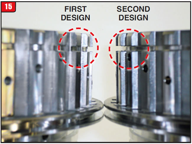
The new package contains a modified clutch drum, 3-5/Rev backing plate and backing plate snap ring. The purpose is to provide a stronger support surface to prevent snap ring pop out. The rotating clutch drum was modified by having a deeper snap ring groove than previous models (Figure 15). The depth of the first design snap ring groove from the outer tooth to the inner tooth was approximately 1.45mm. The groove depth of the new design is approximately 2.35mm which provides a wider surface for the snap. The width of the groove however, basically remains the same.
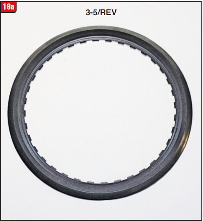
The backing plate for the 3-5/Rev clutch has the teeth at the inside diameter, unlike most other clutch packs (Figure 16a). There has always been a step in the backing plate in order to prevent snap ring pop out, which is why normally the clutch assembly cannot be disassembled from that end of the drum, but requires removal of the snap ring next to the sensor ring.
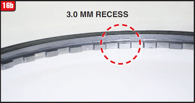
The new design backing plate has more of a recess (step) than the first design (Figure 16b). The tooth width was reduced from 3.5mm on the first design to 3.0mm on the new design plate.
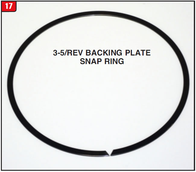
Lastly, the backing plate retaining ring was modified to enhance the other changes. The wall thickness and width were increased to provide a more robust snap ring (Figure 17). The width (thickness) of the snap ring increased from 1.5mm to 1.6mm. All three components must be used as a set, to ensure that there is no stack up or failure issues.
Unlike the 6T70 models, the 6T40 3-5/Rev cushion spring breakage could be the result of the bonded piston design, which is why GM updated the piston. The old design piston could be identified by three small notches cut into the cushion spring surface. The new design is even all around and the part number is 24259061. A new cushion spring part number is 24271971 and should be replaced during any rebuild.
As if previous changes were not enough, GM decided to update the entire transmission in 2012. The new version of the 6T40 is now referred to as GEN 2 and was phased into certain models during 2012, so be aware of which model of transmission is in the vehicle before repair.
Relating to the rotating clutch, just about everything is different from the GEN 1 model. The GEN 2 rotating clutch drum can be purchased under part number 24263999. The drum support (sealing ring support) was also changed from four sealing rings to three and the overall length was reduced.
The drum was modified substantially to accommodate an upgraded 4-5-6 piston design. One outer piston seal is now cut into the drum instead of the piston. The piston return spring set was also modified and is not interchangeable. The new design 4-5-6 bonded retainer has a deeper cavity for oil and has a smaller bore at the snap ring surface. The retainer snap ring is also stepped.
The 3-5/Rev friction material was changed to accommodate the new shift strategy. In addition, the piston return spring set was increased from 27 to 56 springs. The infamous 3-5/Rev clutch cushion spring was also changed. It will be interesting to see how all this unfolds for service.
In conclusion, be aware of not only potential failure areas, but also of design changes before tackling this transmission family.

October 2015 Issue
Volume 32, No. 10
- Volvo 5 speed takeoff glitch
- Dodge Caravan Exchange Surprise
- 6T40 Rotating Clutch Drum Upgrades


