

A customer contacted the shop concerning his 2009 GMC Sierra truck and stated that the vehicle quit moving. He also said that it had not moved when shifted into drive once before; however, it started to work OK later on. The truck was equipped with a 6.6L engine and an Allison 1000 transmission.
The vehicle was towed into the shop, taken off the hook, started up and driven down the road. It had good park-to-drive and park-to-reverse apply and shifted quite well under all throttle positions. The torque converter also had a good lockup.
Right before the shopʼs manager called the customer to tell him that he was in error, it was decided to give it one more shot. Lo and behold, not only did the truck fail to move forward, but it also had no reverse. In addition, the check engine light was on. A scanner was hooked up and trouble codes were pulled. Three codes were set: P0700, P0708 and P0894. The codes indicated a possible problem with the internal mode switch (IMS), transmission slip or TCM. Now the games were on.

The easiest item on the list to test was IMS function. When checking the IMS, shift through all gear ranges and note all four switch positions (Figure 1). Low (or off) means about 0 volt, whereas high (or on) means about 5 volts.
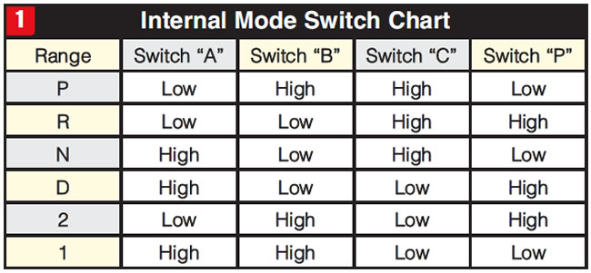
Note: In manual mode all switches should be low (or off).
Test results on the GMC truck were normal and consistent, indicating that the IMS was not the cause of the problem.
The other possibility was ruled out as well, which was the electrical harness. All wires and terminals seemed to be intact and not corroded. The condition of the fluid and pan was also fairly good, which left one main item, the TCM.
A TCM is not routinely replaced and since itʼs a bit tough to test, caution is usually exercised before replacement. In this case, it was a little easier, since apparently GM has had issues with TCMs on 2009 Chevy and GMC trucks. As it turned out, the TCM was bad and needed to be replaced (Figure 2).
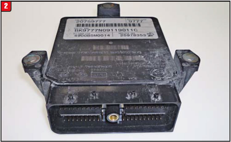

A new TCM was installed; however, that was not the end of it. Unlike on other models, where it can be a plug-and-play installation, once the TCM is installed on a GM truck such as this, a reprogramming procedure needs to be done by a dealer. Another option would be someone who has purchased a reprogramming license from GM.
After the TCM was programmed, the vehicle was driven and worked well, with no erratic-apply issues. Newer computer-controlled transmissions affect garage shifts differently from older models, in that there is no direct connection from the pump to the manual valve to the apply components.
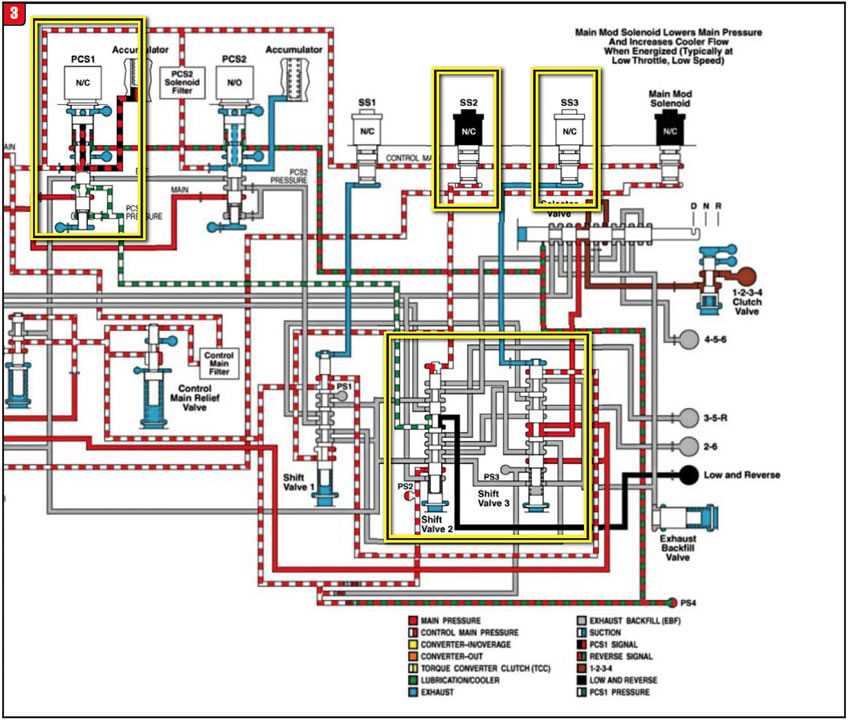
When shifting from park to drive a couple of things need to happen, while other things shouldnʼt happen. For drive range (first gear) to occur, the 1-2-3-4 (C1) clutch and low/reverse brake must apply. Following are the solenoids and valves that are active:
Forward:
A. 1-2-3-4 clutch – The SS3 solenoid is off and the #3 shift valve is in a non-shifted position. If the SS3 were on, clutch-apply oil would be blocked.
B. Low/reverse brake – The PCS1 solenoid is off, sending oil pressure to the #2 shift valve. The SS2 solenoid is on, thus moving the #2 shift valve against its spring and allowing oil pressure to pass through to the low/reverse brake (Figure 3). Any other scenario, and thereʼs no park-to-drive.
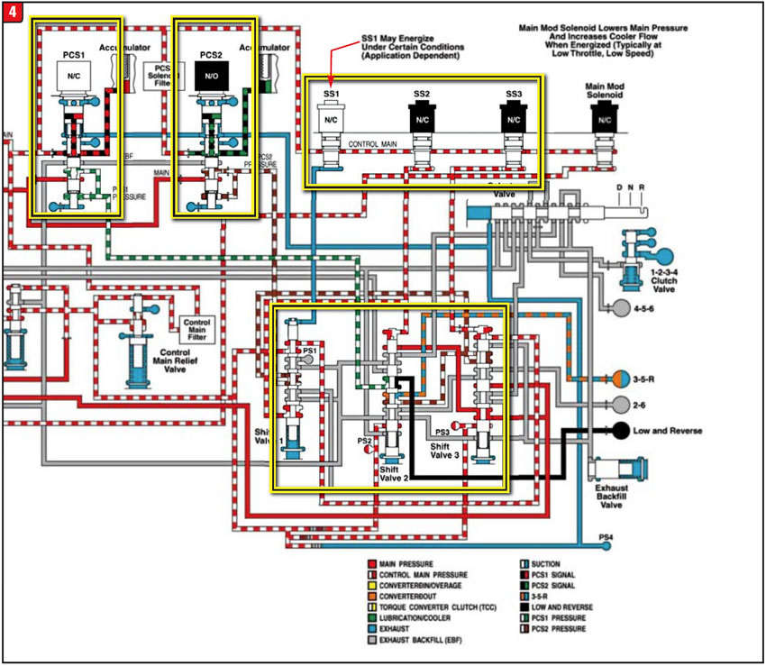
For a shift from park to reverse, the 3-5/reverse brake and low/reverse brake must apply, which involves the following:
Reverse (is even worse):
A. 3-5/reverse brake (C3) – The PCS2 solenoid is on, sending oil pressure first to the #1 shift valve, passing through to the #3 shift valve and finally to the #2 shift valve. From there oil pressure then applies the brake. The three shift valves are controlled by the SS1 solenoid (off), SS2 solenoid (on) and SS3 solenoid (on), respectively.
B. Low/reverse brake – Application of the low/reverse brake in reverse is the same as in drive (Figure 4). Any other arrangement and thereʼs no reverse.
All the listed components are controlled by the TCM, which receives input from the IMS. When things are not in sync, trucks donʼt move.


For decades, rebuilders have been subjected to an endless supply of transmission changes. From a Ford two-speed of the ʼ60s to a nine-speed automatic today (a 10-speed is close), there was one thing in common: They were all step-type transmissions (1-2-3-4 etc.). Whether due to valid increases in fuel economy or pure marketing-driven antics, OEMs started to deviate from the norm by developing different transmission architectures. These new platforms are now on the road in increasing quantities and will at some point show up on everyoneʼs doorstep to be dealt with. How willing or able a shop may be to handle the change is the question.
Of the new breed of automatic transmissions in service today, the CVT (continuously variable transmission) is by far the most plentiful, domestically and overseas. Basically a CVT has two pulleys (variators) that increase or decrease the space between the sheaves (halves) to enable a push belt or chain to “walk” to the inner or outer diameter, thus creating a change in ratio. As with the step-type models, there are various CVT designs to contend with, but the predominant manufacturer today is Jatco, which provides Nissan, Subaru and others with several different variations. The latest version to surface is a CVT with an auxiliary gearbox that, in effect, becomes a two-speed CVT. All things meet in the middle at some point, apparently.
Another emerging transmission technology is the DCT (dual-clutch transmission). It is questionable as to the benefit a DCT has toward fuel economy beyond a regular automatic or standard transmission. A vehicle with a DCT still goes 1-2-3, just like any other step-type transmission, so what is the gain?
In effect, a DCT is two units in one. There are inner and outer input shafts, both of which connect to various gears to provide the different ratios. One shaft would control first, third and fifth gears, while the other shaft would provide second, fourth and sixth gears if the unit were a six-speed. The dual-clutch assembly is what drives each input shaft, alternately.

A “wet” DCT uses a traditional automatic clutch drum that contains a large and small clutch pack that connects to the two inputs. A wet DCT has a pump and valve body along with piston-controlled synchronizer forks to make everything happen.
A “dry” DCT has the same internal gearing as a wet DCT, but with different controls. The dual-clutch assembly is a manual clutch by design but is actually two manual clutches in a modular package. There are two throw-out bearings, two forks and two small electric motors that move the forks. A rather large electric-motor assembly has gears that ultimately shift the transmission forks to change ratios. Everything is computer controlled.
All this is nice; however, to really break the crude-oil stranglehold, a big departure was needed. Enter electric propulsion.
Currently, a golf car with a 300-mile range isnʼt available, so what is “plan B”? To achieve an acceptable trip range, at least up to now, required a combination of power sources: the “hybrid.” A hybrid consists of an internal-combustion engine (ICE) and some kind of electric-motor system, similar to a variable-speed drill (so to speak). A hybrid, or EV, can capitalize on a couple of aspects that can contribute to a decrease in fossil-fuel usage.
As a vehicle comes to a stop, energy is wasted through braking. A hybrid can use regenerative braking to replenish the vehicleʼs power pack.
Second, if so equipped, certain hybrids are plug-in, which means having the ability to access house current to charge the power pack. This option shifts the load from the gas station to the electric company, which produces electricity via different energy sources.
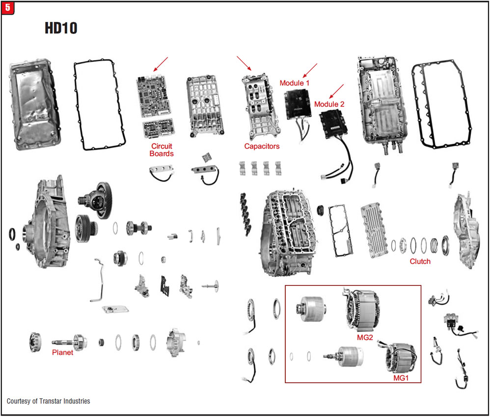
The two main car companies that have hybrid models in any appreciable numbers are Toyota and Ford. Both transmission designs are produced by Aisin Corp. and are somewhat similar (Figure 5). Compared with a normal step-type five- or six-speed automatic, there is not that much iron in an EVT. What distinguishes the Toyota Prius P111 and the Ford Escape HD10 is the inverter. On Toyota, the inverter is external; on Ford models it is integral to the transmission. Items indicated by arrows in Figure 5 represent inverter components not found in the Prius P111.
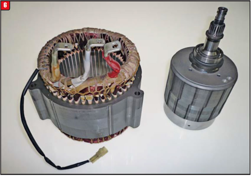
The key components in a hybrid transmission are electric motors. The P111 and HD10 have two, and both act as either a motor or generator, based upon need. The first motor in the stack-up is the MG1 (motor/generator one), which connects directly to the planetary set (Figure 6). The MG1 is used to start the ICE and help it turn, at times, for power. Under certain conditions, the MG1 also generates juice. The armature is supported by ball bearings.
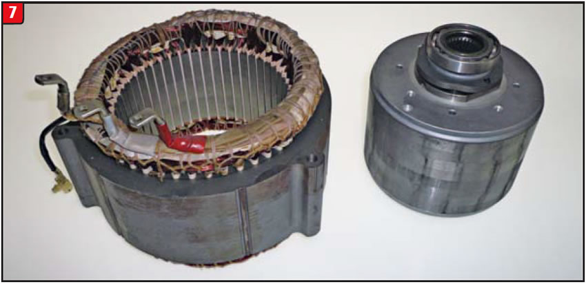
The main drive motor is the MG2 and is the larger of the two (Figure 7). The MG2 splines directly to one of the two drive gears and can propel the vehicle exclusively. Caution should be used when handling both armatures, especially that of the MG2. The magnetic field is so strong that fingers could be pinched between the armature and the metal bench. Keep all metal or electrical items away from them.
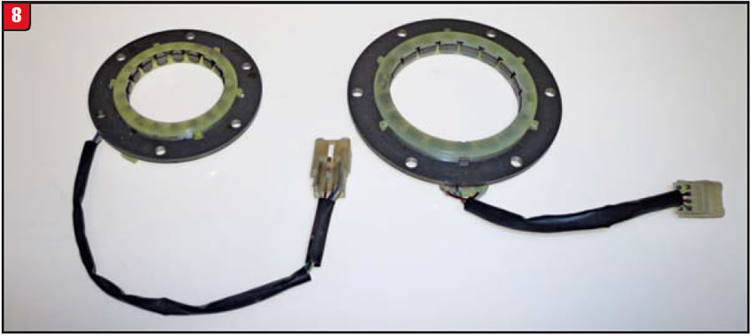
Unlike generators of old, there are no brushes that connect armature output to a source. EVTs use revolution sensors to make the connection (Figure 8). The sensors are bolted to the case assembly.
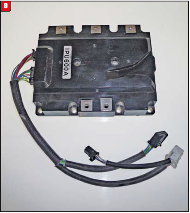
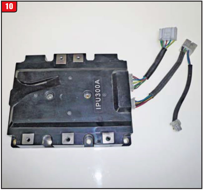
Part of what makes up the Ford HD10 inverter are control modules (figures 9 and 10). The modules are sizable and would require special equipment for testing. The modules are not an issue on Toyotas, since they are not part of the transmission.
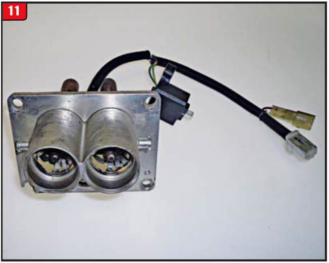
Voltages used by hybrids and EVs are extreme, and if caution is not used during any repair bad things will happen. To illustrate this merely requires looking at the connection (Figure 11). Note the diameter of the electrical-connector plugs. They are large enough to accommodate a transformer mounted to a telephone pole.
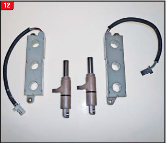
Other do-dads unique to an EVT are terminal blocks (Figure 12). The blocks surround the terminal post and can pick up electrical signals. The blocks are a plastic material and should not be damaged. There are six terminal posts as illustrated in
Figure 5.
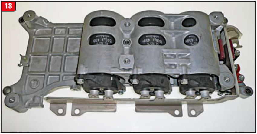
Another inverter component is the capacitor housing (Figure 13). Caution must be used in handling this as well, because of having three 450-volt capacitors, each of which could give someone a good “zap” if not properly discharged. The upside is, capacitors can be tested and, if found to be bad, replaced.
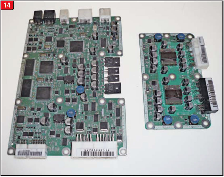
Something rebuilders donʼt run into every day is shown in Figure 14, and these are not from the space shuttle. Both circuit boards are from the HD10 EVT but are not in the Prius P111 or P112 models.
The biggest challenge in servicing or repairing an EVT is proper diagnosis. Beyond that is parts availability. With the volume of these vehicles on the road today, it would be advisable to get up to speed on them. If all else fails, call the TV repair man.

October 2014 Issue
Volume 31, No. 10
- GMC truck with Allison 1000: no forward or reverse movement
- Electric variable transmissions in hybrid vehicles


