


One or more modules are not communicating on the PCI bus, or the entire bus is down.

For individual modules not communicating on the PCI bus system, suspect that either the module is not being powered up, there is an open PCI bus wire to that module or the module is defective. If the entire system is down, the bus wire is shorted to either power or ground.

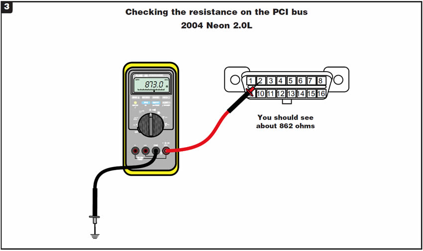
A quick test is to add up all the modules on the bus and check the resistance of all the modules’ terminating resistors at the diagnostic-link connector (DLC). With this particular vehicle, there are eight modules on the bus system (Figure 1). Two of the modules have resistance of 3,300 ohms each, and the other six have 10,800 ohms each.
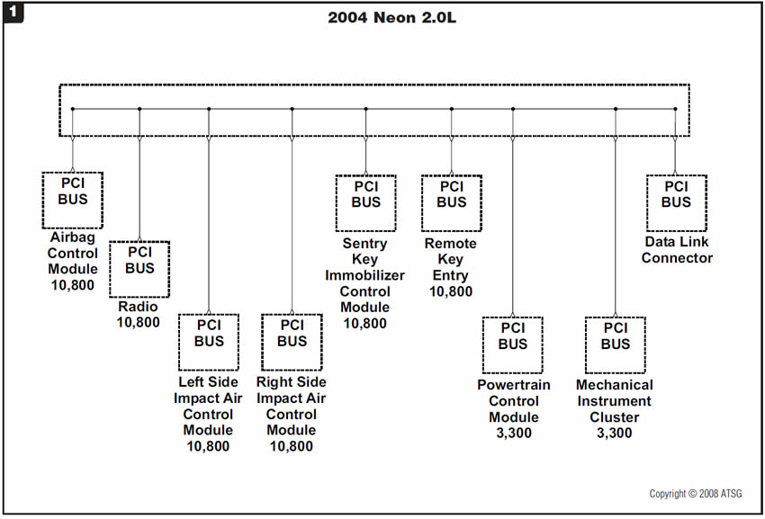
There is a mathematical equation for equivalent resistance in a parallel circuit where the equivalent resistance is added up and divided into 1 as provided in Figure 2.
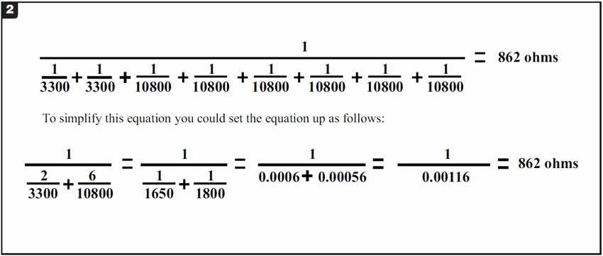
Since we have two 3,300-ohm modules and six 10,800-ohm modules, we do not have equivalent numbers to add up and divide into 1. To acquire that number we would take the two modules that measure 3,300 ohms each and the six modules that measure 10,800 ohms each and turn them into fractions: 2/3,300 + 6/10,800. Before they can be added together these fractions need to be simplified: 1/1,650+ 1/1,800. Now divide the denominator into the numerator and this is what you get: 0.0006 + 0.00056 = 0.00116. It is this number that can be divided into 1, which equals a total of 862 ohms. This is the total resistance of all the modules in the Neon’s PCI-bus circuit and is what you should see at DLC terminal 2 (Figure 3).
If this resistance check shows near 0 ohms the system may be shorted to ground.
If the resistance reads higher, one or more of the modules have lost their grounds.
If the resistance checks good, switch your meter to DC volts, turn the ignition on and recheck terminal 2 in the DLC. You should observe a minimum of 0 to 1.5 volts to a maximum of 6.25 to 8 volts. Anything substantially above 8 volts means the circuit is shorted to power.
If there is a code specifying the module that is failing, check that module’s power source and ground path as well as the terminating resistor at the module itself. Many times, just unplugging and cleaning the connector resolves the problem.
Note: Before making any tests at the DLC with an ohmmeter, let the car sit for an hour to be sure that all the computers are at rest and discharged; otherwise, your resistance readings will be erratic.


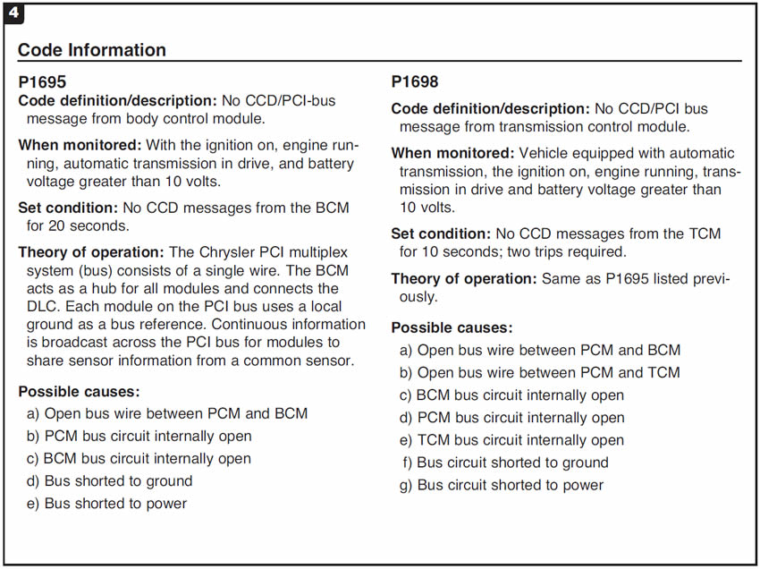
A 1998 Dodge Intrepid with a 3.2-liter engine and 42LE transmission comes into the shop with codes P1695 and P1698 (Figure 4) stored in the computer. Code 1695 is defined as no CCD/J1850 message from the body control module (BCM), and P1698 means no bus message from the transmission control module (TCM).
You also may note that the engine starts and runs well and the transmission shifts properly, yet in the mechanical instrument cluster (MIC) in Figure 5, the tachometer, speedometer and coolant-temperature gauge do not work and the MIL is illuminated, but the fuel gauge is working as well as the PRNDL display, other than when a bus-error message may appear.
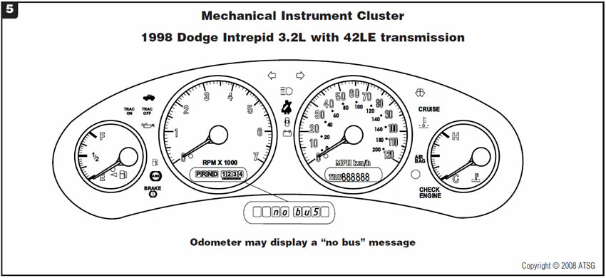
The powertrain control module (PCM) is no longer broadcasting this information to the MIC.
A partial flow chart provided in Figure 6 and wiring diagram in Figure 7 reveal the type of information that is being broadcast and received among the modules. You can see that the PCM broadcasts the RPM, VSS and ECT information and the MIC receives it. You’ll also notice that the BCM broadcasts the fuel-level information and the TCM broadcasts the PRNDL information, both of which the MIC also receives.
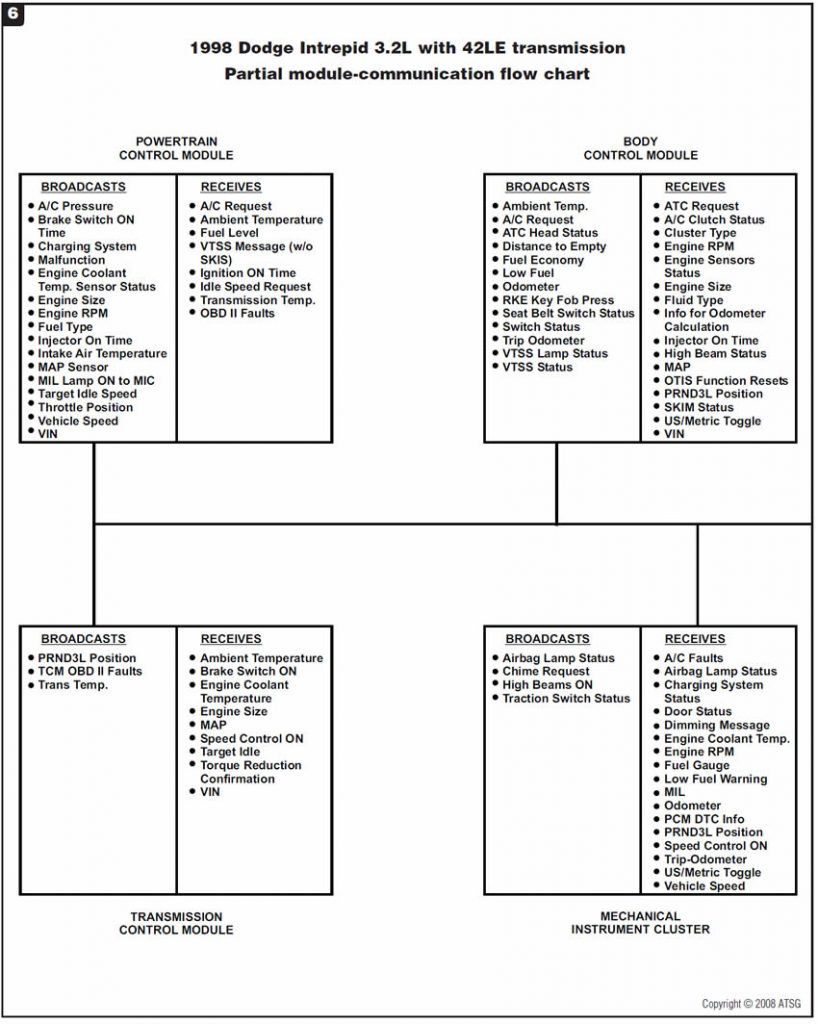
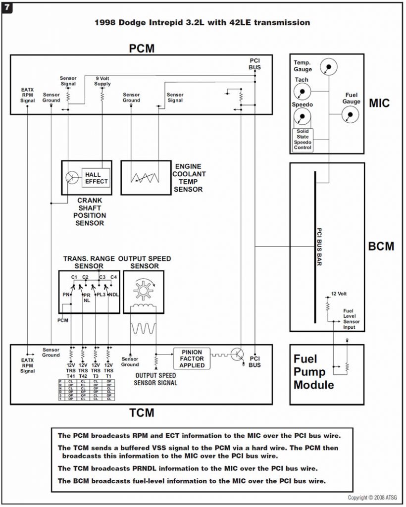
Since the RPM, VSS and ECT gauges are inoperable while the fuel-level and PRNDL displays are, it is sensible to conclude that the PCM is the module having problems communicating with the MIC.
Checking the circuit
Five modules are being used in this 1998 Dodge Intrepid (Figure 8). They are the PCM, MIC, ACM (airbag), TCM and BCM.
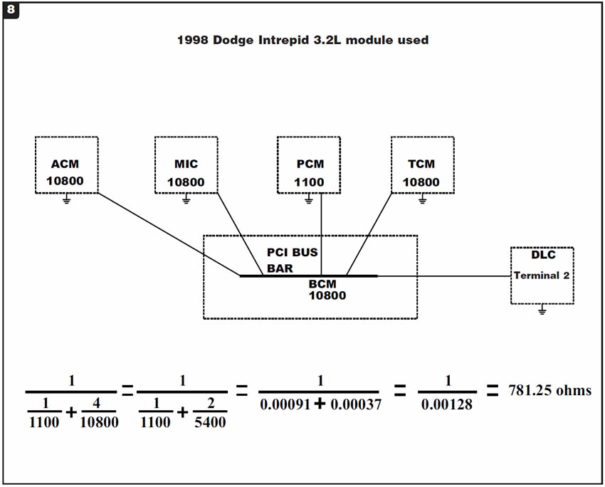
By adding and dividing the resistance of each module on the circuit as shown in Figure 8, you can perform a quick check of the entire PCI circuit at terminal 2 in the DLC (Figure 9). If the entire circuit measures correctly, you can determine that the system is neither shorted nor open and that the PCM itself is defective.
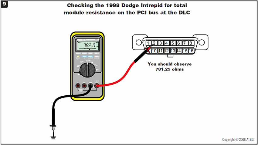
If the entire PCI bus measures correctly, replace the PCM.


October 2008 Issue
Volume 25, No. 10
- 2004 Neon: PCI-Bus Quick Test
- 1998 Dodge Intrepid 3.2L VIN J: DTCs P1695 & P1698


