

The owner of a 2008 CTS was experiencing a transmission problem and decided to take the vehicle to a repair facility. It was equipped with a 3.6L engine and 6L50 six-speed transmission. The vehicle had 93,000 miles on it, was in pretty good shape and the engine ran well. During the road test, the technician did notice a problem with the transmission in regard to shifting into third gear. There was no check-engine light; however, the transmission fluid was not in the best of shape so it was decided to remove the transmission for inspection. With the transmission disassembled, a problem was found with the 3-5/reverse clutch assembly so the customer gave the OK to do the work.
Replacement parts including the torque converter were ordered. The unit was cleaned, prepared and reassembled while using all of the checks and balances. The installer performed all of the routine procedures and installed the transmission back where it belonged without incident. Fluid was then added and the installer hopped into the driver seat with the intent to start the engine and drive merrily down the road. Unfortunately, when the ignition key was turned and the engine started to crank, bad things happened almost immediately in regard to noise, as in banging and clanging.
At first the installer thought that he had left something loose such as the converter bolts, but soon realized that it was much more involved. After ruling out the usual suspects, the focus of the technician turned to an internal-engine concern based upon how it jumped while cranking over. It became real apparent that something major had happened internally, but the question was why.
Whether rebuilding or just repairing an automatic transmission, there has always been specific procedures and precautions that needed to be followed in order to avoid issues at the time or later on. The same was true while doing an R&R of a transmission. A good installer is knowledgeable of all procedures and precautions based upon the application being worked on. There is one aspect, however, that during the heat of battle is sometimes overlooked, and that is which way to rotate the engine to remove the torque converter bolts or nuts. The engine should always be rotated in the direction that it normally runs, clockwise or counterclockwise.
For decades most engines were pretty basic when it came to cam/crank timing. There was a single small gear on the crankshaft that was in line with a single large gear on the camshaft with a bicycle chain in between. As the miles racked up, the timing chain would stretch, creating slop on the downhill side of the gears, but depending on the amount of looseness may or may not cause an issue. If an engine was relatively fresh with minimal chain wear, it really didn’t matter which way the converter was rotated because nothing would happen; however, if the engine was at death’s door with excessive chain slop, rotating the crank in the opposite direction could cause the chain to skip one or more links. Depending upon how many links were skipped, the engine might run rough, not start or worse yet bend valves. Oh how things have changed though, especially with cam/crank timing.
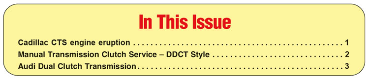
The 3.6L engine in the 2008 Cadillac CTS is but one example. In an effort to improve fuel economy and performance, the 3.6L has VVT (variable valve timing), which involves a massive amount of stuff. The ECM is actually able to control valve overlap via electronics, hydraulics and mechanics. Unlike engines of old, which had just one timing chain, the 3.6L has three
(Figure 1). The potential for a chain to skip a link during a backward rotation has just been multiplied. To make matters worse there are chain tensioners that are hydraulic, which can allow more slack in the chain with the engine off. Apparently, there have been durability issues with the 3.6L timing-chain design due to the fact that it has been upgraded four times.
The purpose of all of this iron is not only due to the fact that the engine is an OHC (overhead cam) design, but also that there are four camshafts that open and close a ton of valves. Add in the issue of computer-controlled variable-position gears and no wonder there is potential for disaster. The overall layout of the engine is absolutely an engineering feat.
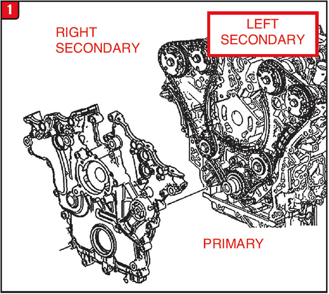
The item that could be considered the starting point of this arrangement is referred to as the primary chain. It is this chain that more closely resembles the drive chain of a regular engine and connects to the crank-shaft sprocket (Figure 2). The primary chain also meshes with two offset intermediate gears that are oil fed. To minimize slop there are two different guides as well as a hydraulic tensioner, and the gears have timing marks.
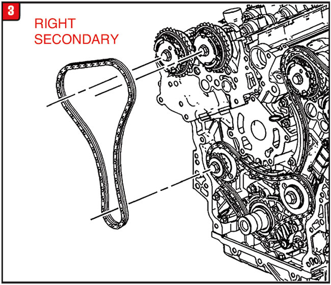
There are two secondary chains that connect the intermediate gears to the four different camshaft gears. The right bank secondary chain is the first chain to be removed (Figure 3). With the right bank secondary chain out of the way, the primary chain can then be removed.
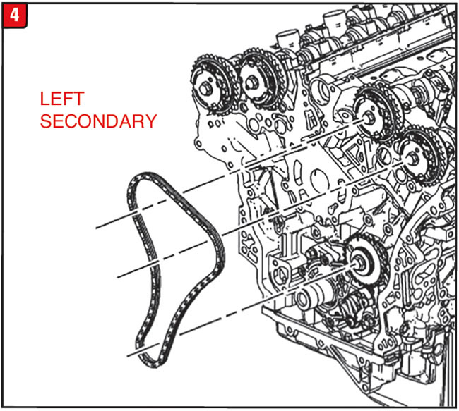
Lastly, the left bank secondary chain is accessible (Figure 4). As with the primary chain, both secondary chains have guides and hydraulic tensioners that must be removed and inspected.
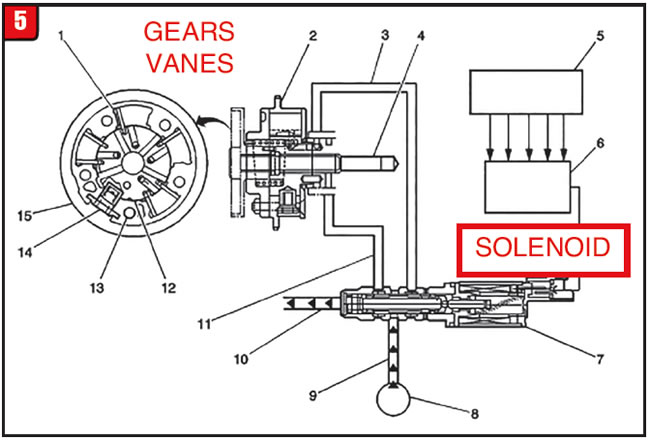
The unique part of the system is the timing chain actuators (variable position gears), all four of them. The gears have internal vanes similar to a GM pump, which react to pressure to change the position of the gear in relation to the camshaft (Figure 5). The ECM sends a signal to four solenoid-operated valves that control pressure going to the gears. There are also sensors that provide feedback to the ECM as to gear position.
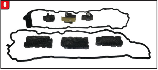
In the event that during an R&R the engine is rotated backwards, skips a link or two and does not bend a valve or break a piston, repairs can be made – but with the question of who’s to pay for it. There are timing-chain kits available that cost a lot and weigh a ton (Figure 6). If a vehicle in for repair has higher mileage on it, advise the customer of this potential problem but, at the very least, always rotate the engine in the right direction.


The first connection between an engine and transmission was the single disc manual (standard) transmission clutch, which consisted of a relatively simple spring-loaded pressure plate, organic material clutch disc, thick flywheel and release components. Although there have been several design changes as well as significant improvements in performance and durability, the layout of standard transmission clutches has remained relatively consistent. Operation of the standard clutch has remained fairly basic as well, in that the clutch disc is normally compressed between the pressure plate and flywheel, uses torsional springs to dampen engine load and has various means to release the disc when needed.
Removal and installation of the clutch assembly on most vehicle applications has not been extremely difficult although there have been a few exceptions. With the transmission out of the way, the hold-down bolts can be removed releasing the pressure plate and clutch disc. Normally when reinstalling the clutch a simple alignment tool is required, but not much more. “So much for the good old days.”
Due to the feeding frenzy of new transmission designs, technicians may find that performing a repair such as a clutch replacement is becoming even more difficult not less. One new transmission design that is gaining traction is the DCT (dual clutch transmission) and not just one version of it. Of the two DCT versions (wet or dry), it is the DDCT (dry dual clutch transmission) that more closely resembles a traditional standard shift clutch, although being just a bit more involved.
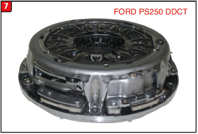
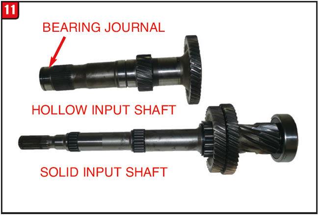
A DCT is basically two transmissions that are crammed into a single housing that provides all the gearing needed to drive down the road. The basis of a DCT starts with two input shafts, one solid and one hollow, which are responsible for driving odd-number or even number gears. The component that drives the two input shafts is the dual clutch assembly. A wet DCT uses a clutch drum assembly that resembles an automatic transmission clutch pack. The driving component in a DDCT, however, is just a bit different from the traditional standard clutch assembly (Figure 7). The Ford PS250 (illustrated) dry dual clutch assembly is a riveted-together modular design that contains two separate clutch discs that are operated by two separate sets of clutch springs.
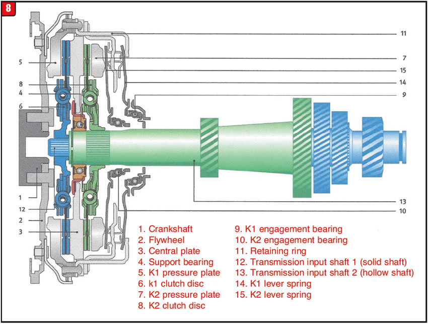
Unlike a standard clutch that uses the throw-out bearing to depress the spring fingers to release the disc, the DDCT assembly spring fingers actually apply one disc or the other based upon the gear selection. The outer set of spring fingers apply the front clutch disc that drives the solid input shaft, and the inner fingers apply the rear disc that drives the hollow input shaft (Figure 8).
The R&R of a DDCT is more in line with an automatic transmission and torque converter than a manual shift transmission and clutch. Unlike the manual transmission design, the DDCT clutch assembly is removed with the transmission. With the transmission out of the vehicle, it should be a simple matter of sliding out the clutch assembly; however, that is not the case. It does require extra effort and extra tooling to merely remove and install the modular clutch from and into the front of the transmission. Ford, among others, offers tool kits to aid in servicing the PS250 (DPS6/6DCT250) DDCT clutch assembly that is used in vehicles such as the 2011-up Ford Focus.
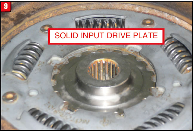
With the transmission bell housing facing up, the first item to be removed is the solid input shaft drive plate, which is held in by a snap ring (Figure 9).
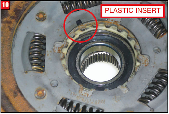
Note the position of the snap ring in relation to a plastic insert that is situated in the groove of the clutch disc (Figure 10). With the drive plate removed, the snap ring for the hollow input shaft is accessible. At this point, proper tooling or another creative approach is required to remove the clutch assembly due to a support bearing being pressed onto the hollow shaft. It may first be necessary to press downward on the bearing to relieve pressure on the snap ring to remove it easily. The press fit of the bearing is noticeable, but not extreme.
With the clutch assembly removed, the input shafts and clutch apply components are visible. In keeping with the DCT design, there are two of everything. The bearing journal on the hollow input shaft is directly in front of the clutch spline with a snap ring groove at the end of the shaft (Figure 11). One issue that has created problems concerning clutch shutter has to do with leaks at one or both input shaft metal-clad seals. Any time that the clutch assembly is removed, both input shaft seals should be replaced and there is a special tool to do it, of course. The seal kit part number is EV6Z-7052-C.
Clutch-apply (not release) components are not exactly duplicates. There is a large and small throw-out bearing that contacts the clutch apply spring fingers, which comes as a single assembly. In addition, there are two thrust plates that go between the throw-out bearings and spring fingers for support (Figure 12).
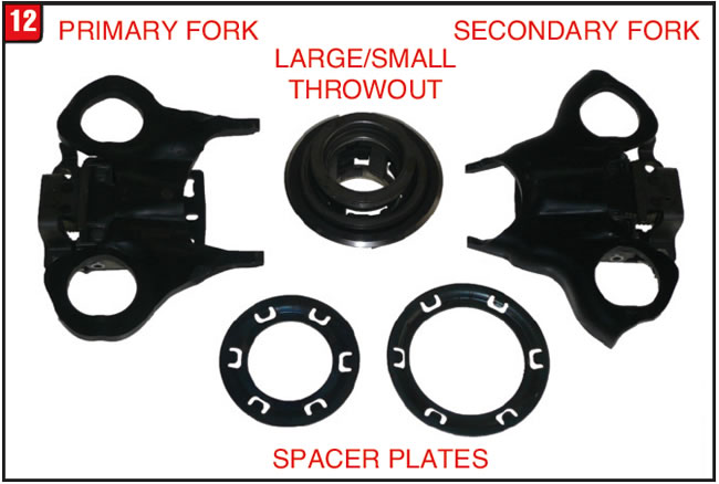
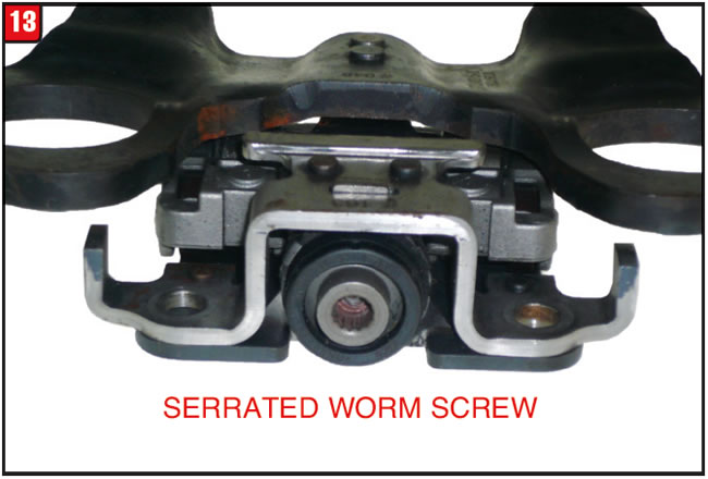
There is also a large and small fork that applies the corresponding throw-out bearing that has special spring-loaded hold-down bolts to enable movement. Unlike a traditional standard transmission clutch that has used rods, cables and hydraulics to operate a throw out bearing the DDCT forks are electrical. The forks use worm screws to move rollers up and down ramps in order to apply the clutches, and the screws are serrated at the end to mesh with the electric motors (Figure 13).
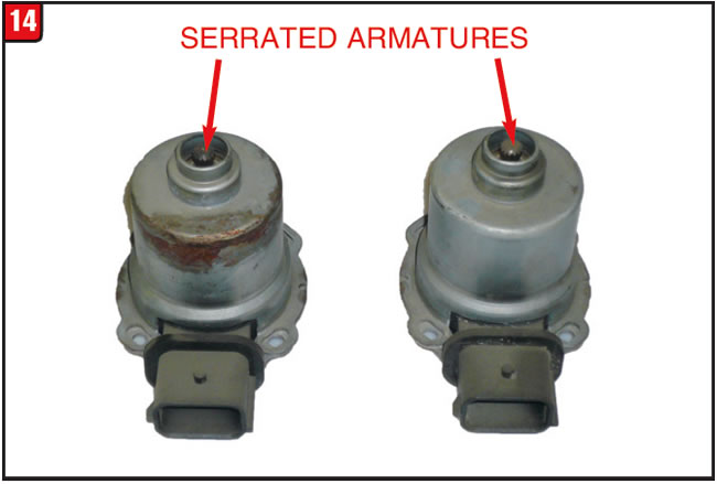
The two electric motors that operate the clutch forks are the same design and are very sensitive. The motors bolt to the outside of the bell housing and extend through to mesh with the forks. The armature of each motor is serrated at the end, which is what contacts the fork worm screw (Figure 14). The motors have to be controlled precisely to provide the correct apply, release, hill hold, etc. Once everything has been inspected or replaced the dual clutch assembly can be installed.
There are two different procedures to follow when installing a clutch assembly depending on whether a new clutch is installed or the original clutch is reinstalled. Installing a new clutch assembly is actually easier than installing a used one because the new assembly is provided with the clutch-apply springs in a pre-loaded state. The spring fingers on a used assembly must be put into a locked position, which is no small thing. There is of course a separate tool kit to accomplish the task. The part number for the new dual clutch assembly is F1FZ-7B546-B and lists for about$400.
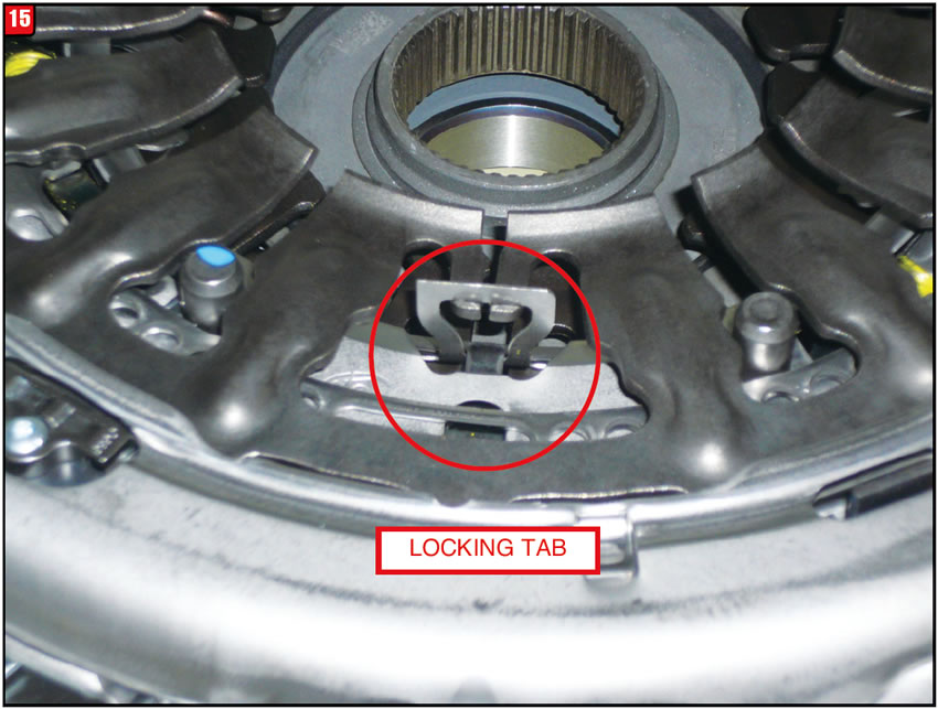
Using the proper tool or other means, press the primary (outer) fingers down far enough to engage the three locking tabs (Figure 15). The locking tabs will hold the fingers in the correct position during assembly. Next use another chunk of the tool kit to press down and lock the secondary (inner) fingers, which are even more difficult than the primary fingers.
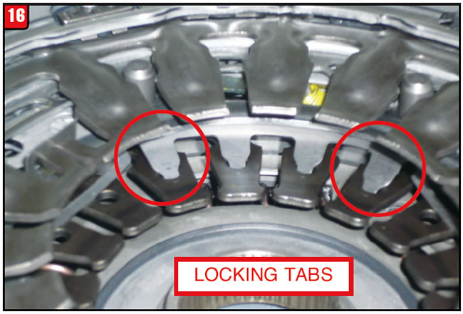
There must be a minimum of six locking tabs to engage the fingers in order for it to work correctly (Figure 16). The tooling involved in these procedures includes the holding fixture, a threaded rod and adapters.
Whether new or used, at this point the dual-clutch assembly is ready to be installed onto the input shafts. The assembly can either be pressed or tapped into place, depending on preference. Once in position, the hollow shaft snap ring can be installed then the solid shaft drive plate and finally the drive plate snap ring, making sure that the gap is aligned with the plastic insert. Lastly, the spring fingers must be unlocked. With the electric motors removed a tool can be inserted into the fork worm screws and rotated counter-clockwise approximately 10 to 14 turns. Once done, both worm gears can be returned to the beginning position.
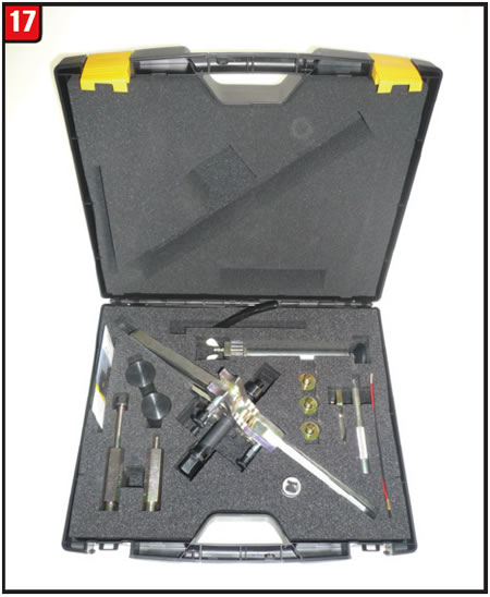
Ford does offer the tool kits to not only remove and install the dual clutch assembly but also to provide a means to preload the spring fingers, both of which are quite costly. One alternative to the OE tool kits is produced by LuK, which is the company that makes the dual clutch assembly. The tool kits provided by LuK not only fit Ford applications but are also available for VW and Renault. The basic remover/installer tool kit is LuK part number 400-0418-10 (Figure 17).
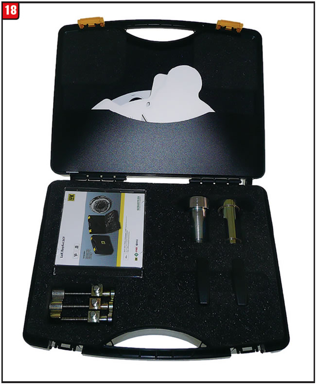
The specific sub kit for Ford applications is LuK part number 400-0427-10 (Figure 18). A LuK tool kit is available for spring finger compression under part number 400-0425-10.
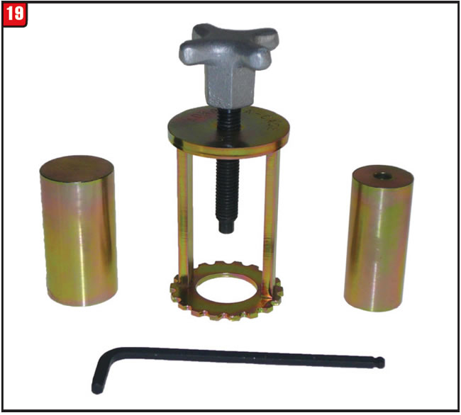
Adapt-A-Case has just recently released a tool kit that applies to Ford applications and is utilized to remove and install the clutch assembly (Figure 19). The Adapt-A-Case part number is T-DPSCAC.
No matter the approach working with this family of clutch assemblies, whether it be diagnosis, repair or replacement, greater patients will be required. Once the job is completed, computer relearn and break-in procedures must be followed to avoid drivability and durability issues.


This is an update to the October 2016 Audi 20 0B5 Transmission Tech/Talk newsletter article concerning the dual-clutch assembly. As stated in the article, certain components of the dual-clutch housing are welded together during manufacturing, which would normally prohibit replacement of the K1 clutch apply piston. An alternate approach is available, however.
Alto, the friction manufacturer, has developed a tool to enable replacement of the K1 piston by separating the sealing ring sleeve from the housing assembly (Figure 20). The sealing ring sleeve presses onto the rear part of the housing and the pump drive gear presses onto the sealing ring sleeve. Caution must be used during removal or replacement of all components.
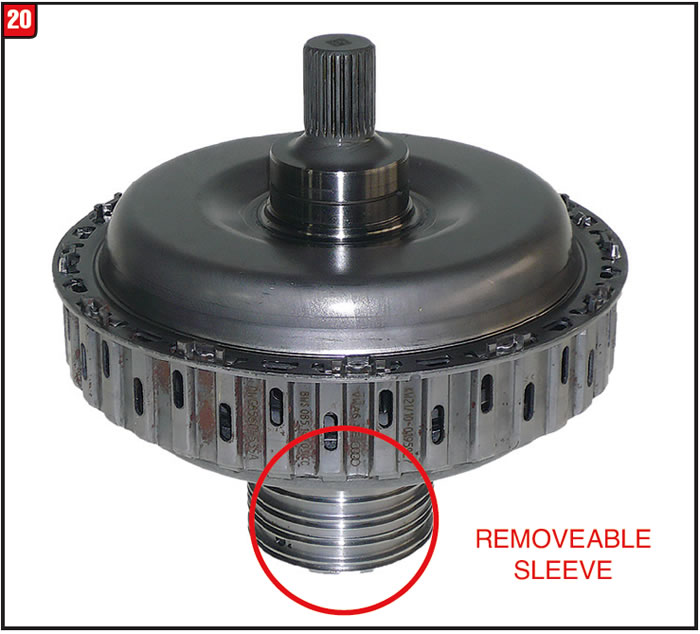
A good set of press jaws can be placed in between two of the sealing ring grooves, and using a suitable puller the ring sleeve can be removed from the housing. Note the position of the sleeve in relation to the oil holes of the housing. With the sleeve removed, the K1 apply piston can be replaced.
Carefully follow the directions provided with the Alto tool in order to correctly reinstall the sleeve. Both the K1 and K2 bonded rubber apply pistons are available.

November 2016 Issue
Volume 33, No. 11
- Cadillac CTS engine eruption
- Manual Transmission Clutch Service – DDCT Style
- Audi Dual Clutch Transmission


