


A customer with a 2006 Mercedes CLK500 was sailing merrily down the highway when all of a sudden there was a noise. The engine started to race and the vehicle had to coast to the berm. The customer had to call a wrecker because of no movement and was not thrilled, since it had only 85,000 miles on it. The vehicle was equipped with a 5.0L engine and a 722.9 seven-speed transmission.
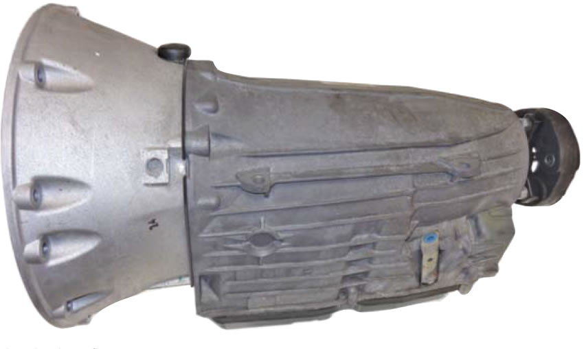
Once the vehicle arrived, the basics were checked (fluid, trouble codes etc.). A pressure gauge was hooked up first and then the pan was dropped. There was no line pressure and the pan did have some debris. At that point, the unit was peeled to determine what the problem was.

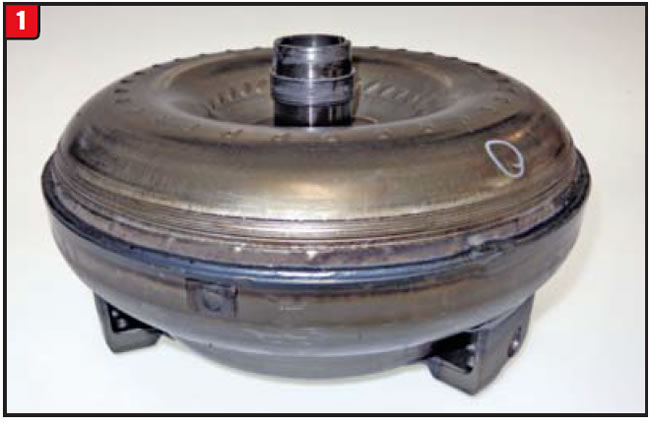
Once the transmission was removed, the torque converter was pulled, and “voila” – case solved. The bushing was literally welded to the hub, which meant the pump was trashed (Figure 1). The rest of the transmission was disassembled as a precaution and appeared to be in fairly good shape, considering the mileage. The question is, why did the pump bushing seize to the converter hub and spin out?
Normally, a vehicle untouched by human hands does not spin out pump bushings without a good reason. The challenge was to determine why this one did.

The 722.9 was launched in 2004 and has been increasing in model usage ever since. The basic layout is the same as that of the 722.6 five-speed with a few exceptions such as an extra clutch pack and renaming of others. The front-planet set has an additional ring gear to provide the extra ratios.
The biggest departure from the 722.6 is the valve body, of course. Not only are there two additional solenoids, but also the 722.9 has an integral TCM, which makes it a mechatronic valve body.
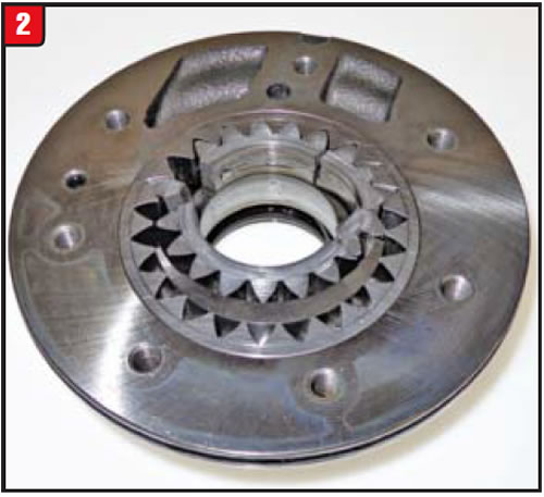
The pump configuration is the same between the 722.6 and 722.9; at least, it started out that way. Both transmission pumps were equipped with a bushing, which worked out fairly well on the 722.6 but not so well on the 722.9 (Figure 2).
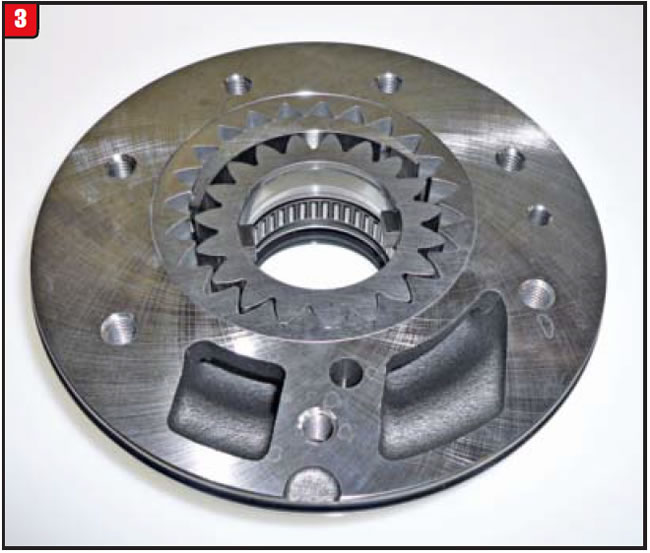
Bushing spin-out and pump failure can be caused by several problems; however, there were enough occurrences on the 722.9 that Mercedes chose to switch from a bushing to a caged bearing some time ago (Figure 3). The bearing design is the only one available from Mercedes (part # 722 270 0197).
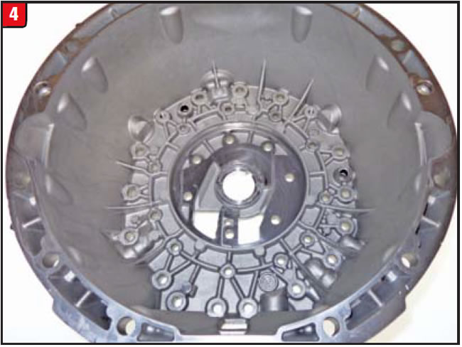
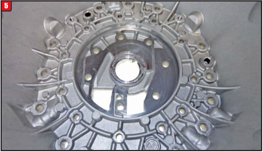
Unlike other transmission models that use a similar pump/bellhousing setup, the Mercedes 722.9 pump gears ride against the bellhousing directly, not a steel pump plate. That means when the pump bites the dust, the gears can eat into the face of the bell (figures 4 and 5). When that happens there are a couple of options. If the wear marks are not too deep, the housing can be milled and be reused. Second, if the grooves are too deep, the housing may need to be replaced.
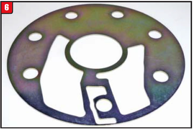
Recently, a drop-in steel pump plate has become available from Exedy, the clutch-plate folks. Before using the plate (Figure 6), make sure that there are no raised areas or indentations on the housing surface. When switching from a bushing- to a bearing-design pump, another concern must be addressed: the torque-converter hub. Regular converter hubs can accommodate bushings like bronze, Babbitt or Teflon; however, the hub may not be hard enough to act as a bearing journal for the new-design pump body. Inform the converter rebuilder that the pump has a bearing to ensure that the hub hardness can handle it, or the vehicle could be back in no time with a worn hub.
Before installation of the transmission, certain things need to be checked, such as the converter-to-crankshaft-pilot clearances and the engine-to-bellhousing lineup pins. Also, make sure that the clearance between the flywheel and mounting pad is correct. Another possible issue can be electrolysis due to bad grounds. Arcing can occur at a bushing and cause failure if the vehicle does not have good grounds. Last, do a thorough radiator flush to remove all debris and avoid a pump-failure replay.
Do the upgrades, follow procedures, check related components, and the unit should live.


Ideally, when a vehicle shows up for a repair to be done, symptoms would point to a singular cause, but such was not the case when a customer brought in his 2005 Chrysler 300. The vehicle was in limp mode with the check engine light glaring back. Codes were pulled using a scanner and there were two: P1775 and P1776. Beyond that, both codes refer to multiple potential causes including:
- Transmission control relay open
- Low/reverse pressure switch open/short
- PCM issue
- Solenoid switch valve malfunction
That information certainly narrows the playing field, which makes for a simple fix – or not.
The codes were erased and the vehicle was driven again. The transmission worked well – for a while, that is – but went back into limp mode with the check engine light on.
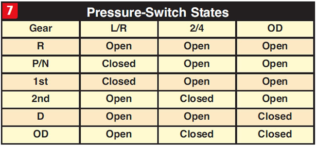
To diagnose is to divide and conquer, by jumping on the easiest items first. The external stuff is usually what to go to at the beginning, so that was the starting point. The TC relay was checked and appeared to be OK along with the harness wires. The next item on the list was the low/reverse pressure switch. Instead of pulling the pan and valve body, the technician hooked up a scanner again to test for pressure-switch readings. All three pressure switches seemed to function as intended. The chart refers to the open/close state of each pressure switch (Figure 7).
Although the PCM is external, it is not a simple matter when it comes to diagnosis. Itʼs more a matter of ruling out everything else, leaving only the PCM being the bad guy. Initially, items surrounding the PCM (connectors, wires etc.) seemed to be intact. Due to the erratic nature of the problem and history of the A604 series of transmissions, the valve body was pulled to check the solenoid block and solenoid switch valve. Everything appeared to function correctly; however, an issue could have still existed, although not apparent.
Since nothing was obvious once the valve body was pulled and checked, backtracking was called for. A closer look at the PCM connection revealed a corroded harness wire that was somewhat tough to spot. The wire was repaired; however, there was still the question as to whether the valve body was an issue, especially with the problems of the past relating to the solenoid switch valve. As a precaution, the valve was replaced.
Of the handful of valves in a 42RLE valve body, the solenoid switch valve is the most involved and troublesome. At least the valve has remained unchanged during valve-body upgrades.
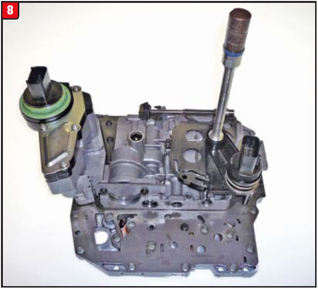
The 42RLE was released in 2003 Jeep models and the valve body was basic like the A604 (Figure 8). The solenoid block bolts to the valve body, unlike in the A604, but functioned the same.
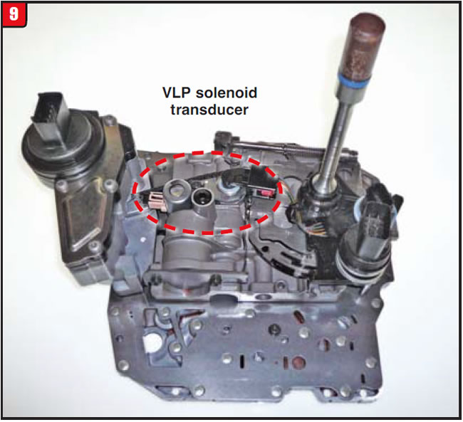
Chrysler decided better controls were needed, however, and added more stuff in 2006 and renamed it 42RLE VLP (for variable line pressure). A line-pressure solenoid and pressure transducer were now part of the valve body (Figure 9). The solenoid block remained unchanged. The A604 (41TE) got the same facelift in 2007 and was renamed 41TES.
The solenoid switch valve and plugs have more than one function and are controlled by different pressure sources. Basically, the valve controls how and when the low/reverse clutch applies as well as the torque-converter clutch. The position of the valve dictates which component is affected.
Apply pressure is fed to the valve from the LR/CC solenoid (S3) and passes through to the proper component, based upon valve position.
Control pressure for the valve stems from pump pressure on the left side, whereas control pressure from the right can come from the UD solenoid (S1), 2-4/LR solenoid (S4) or OD solenoid (S2) based upon demand.
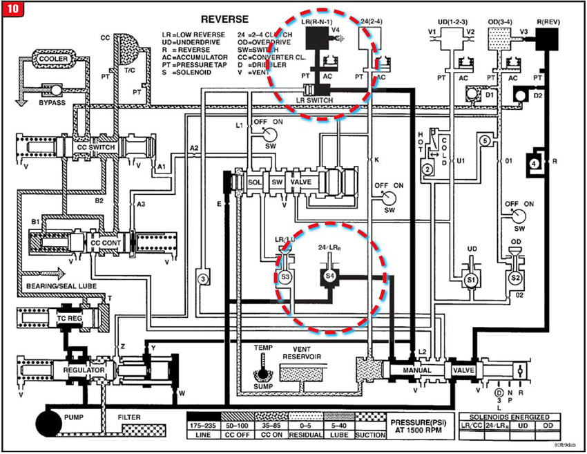
Reverse – Although the low/reverse clutch is applied in reverse, the solenoid switch valve has no part in the operation. Oil pressure merely passes through the 2-4/LR solenoid then passes through the manual valve to move the L/R switch valve to the left and apply the clutch (Figure 10).
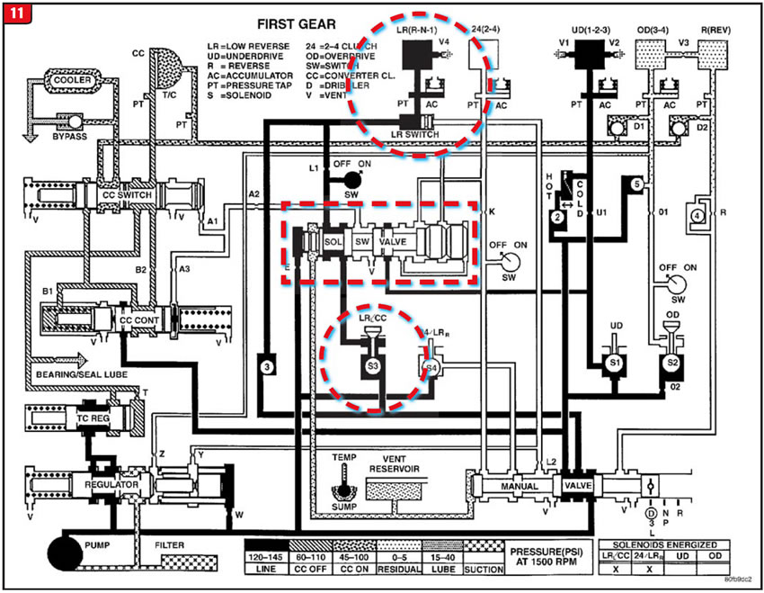
Drive 1st gear – The low/reverse clutch is applied in neutral and first gear, but from a different direction than in reverse. Oil pressure is directed from the manual valve through the LR/CC solenoid, through the switch valve to ultimately apply the L/R clutch (Figure 11). Regulation of the apply pressure comes from the LR/CC solenoid duty cycle.
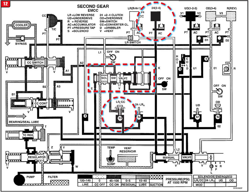
Drive 2nd gear with lockup – The low/reverse clutch must release for 2nd gear and conditions be set for lockup to work. A couple of things must happen to transition to 2nd gear. The LR/CC solenoid must close, cutting off pressure to the switch valve. Next, the 2-4/LR solenoid opens, sending oil pressure through the manual valve to the 2-4 clutch and also to the right side of the switch valve, moving it left and allowing the L/R clutch to exhaust. Underdrive-clutch pressure also works to latch the switch-valve plugs.
Once the unit is in 2nd gear, lockup can be applied by the LR/CC solenoid sending oil pressure through a different passage of the switch valve to the converter-clutch switch and control valves (Figure 12). Lockup apply is controlled by the solenoid duty cycle and CC valves.
During the transition to third, the switch valve is also held left via the OD solenoid acting upon the switch-valve plugs. Fourth gear reintroduces the 2-4 clutch scenario. There is a lot of action at the switch valve.
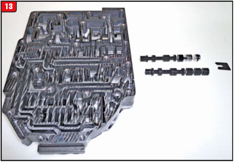
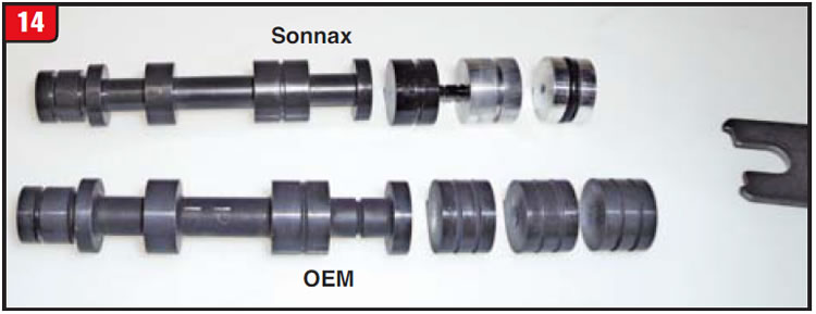
It is imperative to closely check the switch valve and plugs on any 41TE/42RLE-type valve body. They all stack up the same (Figure 13). There are two valve trains shown in Figure 12; the lower one is OE and the upper one is Sonnax.
To install a replacement valve, which is oversize, requires reaming the bore. Unlike the OEM design, which has three plugs of the same type, the replacement setup uses two plugs that are piloted for support and an end plug with an O-ring for sealing (Figure 14).
Erratic conditions can involve more than one item, so pick the right one, but be aware of the others.
Special thanks to Avi Segal from Cottman Transmission, Austin, Texas, for recommending that this issue be covered.


A customer with a 2005 Cadillac DTS was experiencing an intermittent transmission-fluid leak from the left side of the vehicle. It would not leak sitting still but needed to move in one direction or another.
The vehicle was equipped with a 4.6L engine and 4T80-E transmission and had 78,000 miles on it. The unit seemed to work well and had no trouble codes. Upon inspection of the transmission, it appeared that the fluid leak was coming from the left-side axle seal (no surprise), but in addition, it looked as though someone had replaced the seal previously. When questioned about it, the customer said the vehicle had been to another repair facility for other work and he thought something had been replaced on the transmission.
The previous shop obviously saw the wet area around the left-side axle seal and merely assumed that the axle shaft could be popped out and a new seal installed. The leak was not due to the axle seal being bad but rather excessive movement of the axle shaft itself.
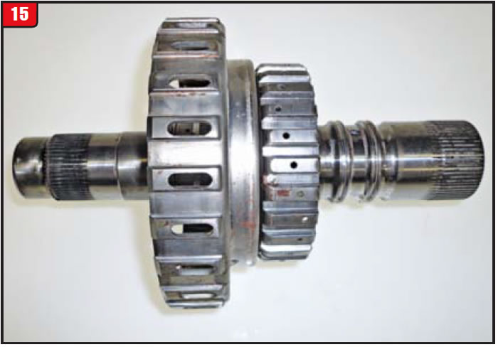
As has been the case with other transmission types, when the bore that an axle journal rides in wears to a certain extent, shaft movement exceeds the metal-clad sealʼs ability to work. The bore that the axle shaft rides in on a 4T80-E happens to be the third-clutch housing (Figure 15). The unit was removed to inspect for internal damage.
Although the transmission worked well on the road test, there were signs of slippage in the forward- and second-clutch packs, most certainly due to a low-fluid condition before the seal was replaced. The main issue was, of course, the third-clutch-drum bushing and axle-shaft journal.
Normally, to address this type of wear would require merely replacing the bushing with a service bushing. However, third-drum bushing wear on a 4T80-E tends to be more prevalent. The drum bushing in the Cadillac DTS had a fair amount of wear and scored the axle shaft enough to require replacement.
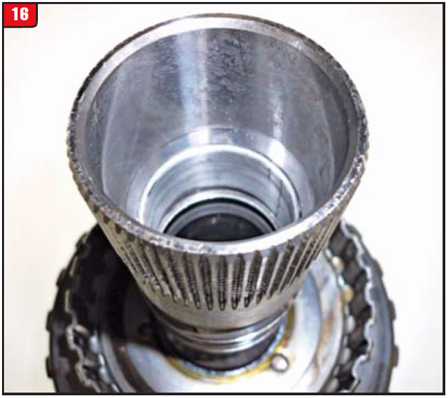
Based upon the rate of failure, GM issued a replacement third drum with an improved bushing material, part # 8682114. A way to distinguish the upgraded bushing material from previous types is the color. The new material is whiter, unlike older materials such as bronze (Figure 16).
Bushing materials have been changing over the years for other reasons. Some time ago, the EPA started banning lead from certain bushing materials, which resulted in a different look. Domestic bushings were primarily either bronze (gold-looking) or Babbitt (aluminum-looking). Overseas bushings also were bronze but were aluminum based as well with a more-whitish color. The new domestic bushings look more aluminum than bronze, or even Babbitt.
It remains to be seen how all this change will affect durability and cost, but change is inevitable.

November 2014 Issue
Volume 31, No. 11
- Mercedes 722.9 failure
- 42RLE DTC variations
- 4T80-E fluid leak


