Technically Speaking
- Author: Wayne Colonna, Technical Editor
A 1995 Lincoln Continental with an AX4N transmission comes into the shop with a gear-ratio-error code. As you are going through the diagnostic routine, you have pretty much determined that the unit needs to come out. But before you remove it, you decide to check for a glitch in the vehicle-speed sensor (VSS).
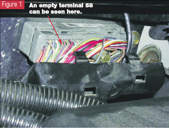
In most instances with an EEC-V system, terminals 33 (-) and 58 (+) are the VSS wires to the PCM’s 104-pin connector. After locating these terminals (center of the firewall – see Figure 1), you discover that they are empty. You obtain a wiring diagram and review it, only to confirm that no VSS appears there, either.
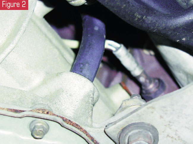
You then put the car up on the lift to look for the VSS. You can see nothing other than an oxygen-sensor wire (see Figure 2). Even when you try to feel for the sensor, it is no where to be found.
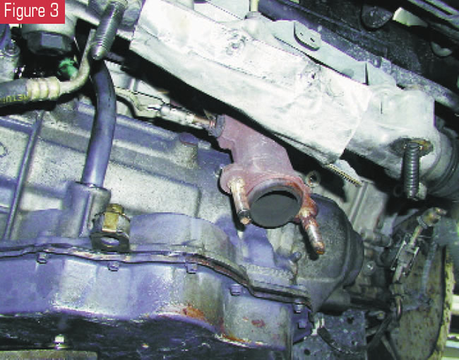
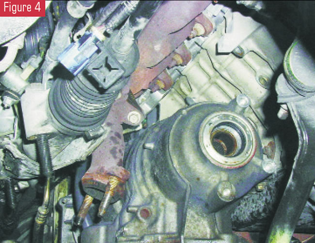
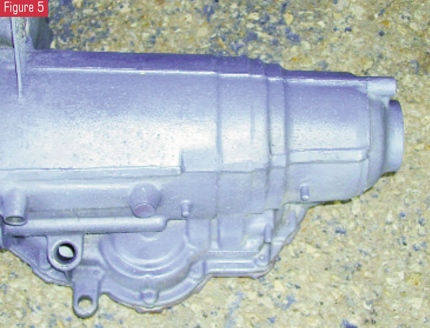
So you make the final decision to remove the transmission, and, of course, there is no VSS on the transmission (see figures 3 through 5).
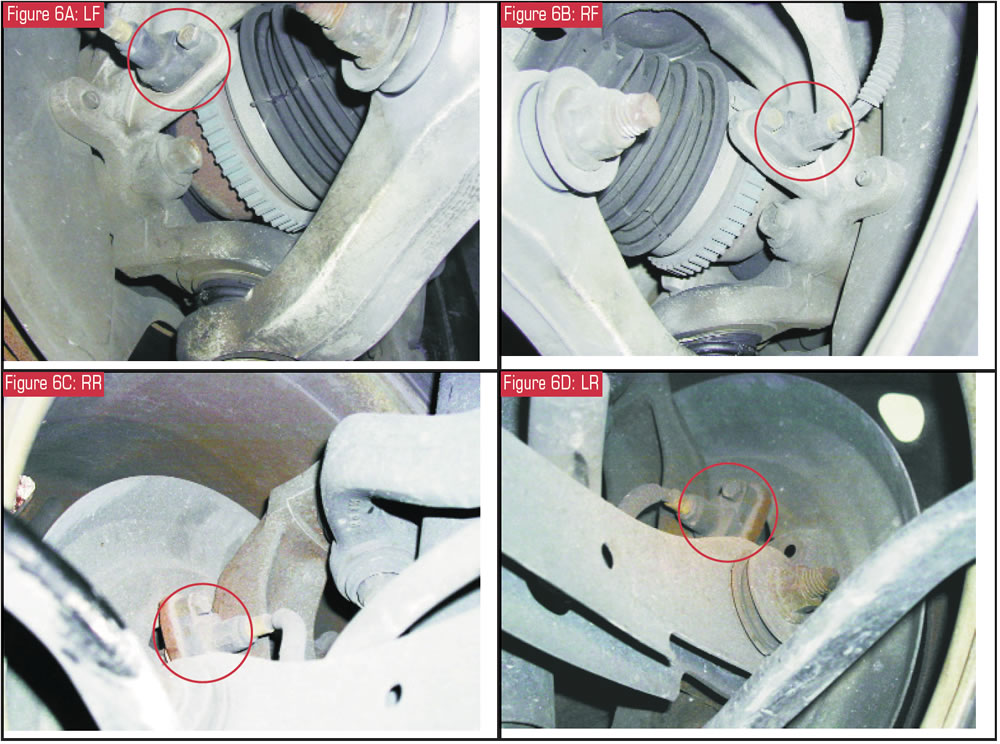
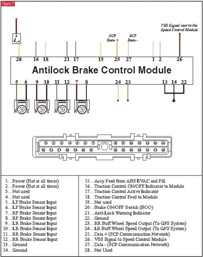
So where does the vehicle-speed signal come from? For 1995 to 2002 4.6-liter Lincoln Continentals, it comes from the antilock-brake-system (ABS) control module. This module receives the signal inputs from the wheel-speed sensors (see Figure 6) and converts them to a vehicle-speed output of 8,000 pulses per mile for the vehicle speed-control module (see Figure 7). It also broadcasts this information over the SCP (standard corporate protocol) communication network to many multiplex modules, such as the powertrain control module (PCM), the virtual image cluster (VIC) and the vehicle dynamics module (VDM).
Should an erratic speed signal or loss of vehicle-speed signal occur, the ABS light will certainly be illuminated in the VIC (a very impressive dash). To track down the cause effectively, you will need to diagnose the ABS, and in most instances this will require an ABS cartridge for your generic scan tool.
It is fascinating to consider that this ABS control module (regardless of whether the vehicle is equipped with traction control) can produce an accurate vehicle-speed signal even during turns or when the ABS becomes active. It must aggregate the data from all four wheel-speed sensors by taking into account an inside tire turning slower during a turn or while the ABS is activated, pulse-braking a tire or two. And then having this calculated vehicle-speed signal broadcast over the network allows the PCM to receive and use this information in part to determine shift timing, transaxle gear ratio and percentage of TCC apply by comparing it with the signal from the turbine-shaft-speed (TSS) sensor. It is an amazing and intelligent system, to say the least.
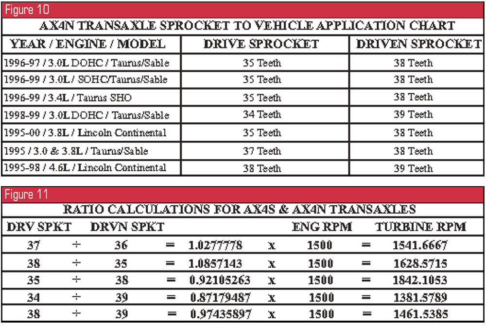
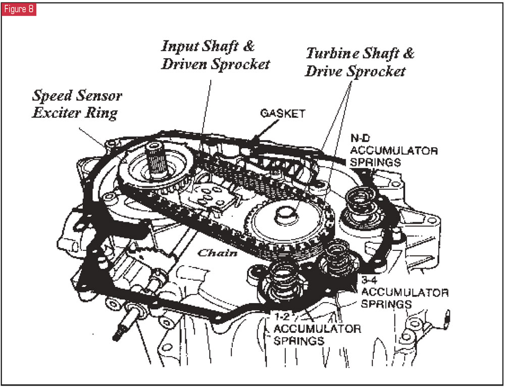
As an additional note, when it comes to the PCM determining gear ratio, this becomes another interesting calculation, as the TSS sensor is not reading the speed of the turbine shaft. What it does read is the input speed to the transmission from the four-tang exciter ring on the driven sprocket (see Figure 8). With the turbine shaft being an integral part of a 38-tooth drive sprocket in a 4.6-liter application, it delivers power to a 39-tooth driven sprocket via the chain. This means that the driven sprocket (the input speed to the transmission) is not spinning at the same speed as the turbine shaft. When the turbine shaft and 38-tooth drive sprocket spin one complete revolution, the driven sprocket rotates just slightly less than one. By dividing the driven-gear tooth count (39) into the drive-gear tooth count (38), you can determine the rotation of the driven gear relative to the drive gear. The input shaft makes 0.97435897 revolution per one revolution of the turbine shaft.
Taking it to the next level, if the converter clutch is fully applied and not slipping while the engine speed is about 1,500 rpm, the turbine shaft and drive gear also will be at 1,500 rpm, but not the input speed (driven gear) that the TSS sensor is reading. To determine what the approximate speed read by the TSS sensor should be, multiply 1,500 by 0.97435897 and you will arrive at 1,461.5385 rpm. That is the actual rotation speed of the driven gear when the drive gear is at 1,500 rpm. The PCM is programmed for this particular application so that it knows to make these calculation adjustments to determine whether the converter clutch is slipping.
By making similar calculations, the computer also can determine gear ratio by comparing it with the vehicle-speed signal it receives over the network from the ABS control module. It’s astounding to consider how the PCM is calculating drive- to driven-gear ratio and comparing it with a calculated vehicle speed it receives from the ABS to accomplish so many tasks. The multiplex communication system in these Continentals is a very sophisticated system, and this is just a small glimpse of its intelligence.
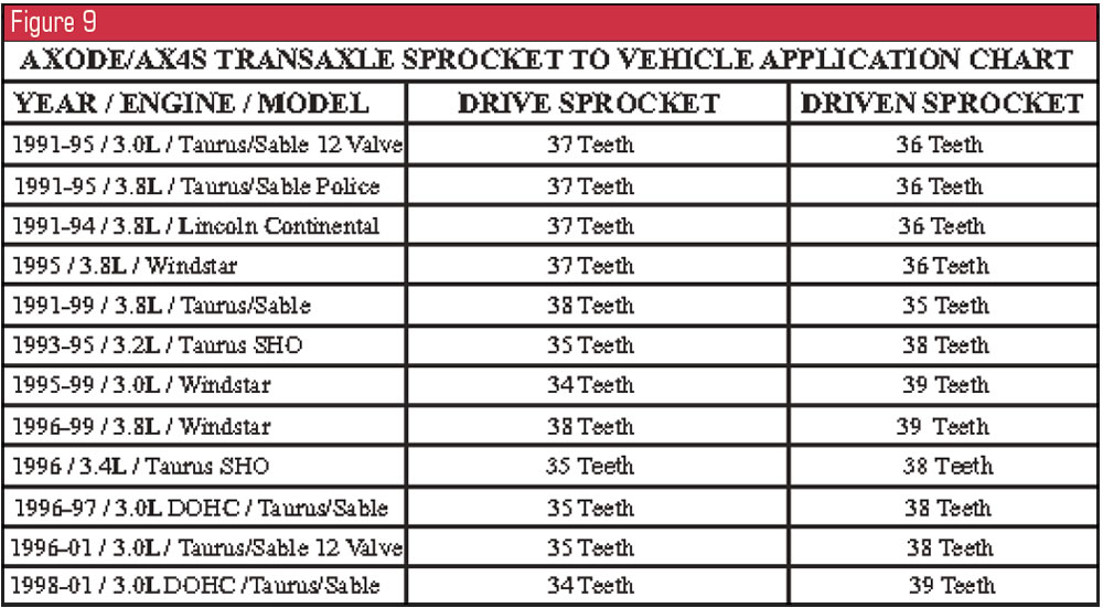
Figures 9 and 10 provide drive- and driven-gear tooth counts for various AX4S and AX4N applications. Figure 11 provides completed calculations of what the TSS sensor should read when the converter clutch is fully applied with engine speed at 1,500 rpm.