Torque Converter Tech Tips
- Author: Ed Lee
Last in a four-part series on torque-converter modifications
In the past three articles we looked at the evaluation of torque-converter modifications on a chassis dyno. The modified converters were compared with an OEM converter, and the testing was done by instructor Sean Boyle and three of his students at Southern Illinois University. An MD-250 Mustang Chassis Dyno was used for the evaluations, and a Dodge Durango RT, equipped with a stock 5.9-liter gas engine and 46RE transmission, was used as the test vehicle. All the converters were subjected to wide-open-throttle (WOT) horsepower tests. The vehicle was locked in third gear (direct drive) and TCC lockup was inhibited.
The first modified converter tested (converter A) had its stator modified in a manner that lowered the stall of the converter, and the vehicle responded favorably. The modification probably would have enhanced the vehicle’s fuel economy and towing capabilities. The next two converters, B and C, had modifications that raised their stall. Converter B had 0.175 inch machined from the turbine side of the stator. Converter C had its internal clearance (impeller to turbine) doubled, from 0.080 inch to 0.160 inch. Both of these converters may have been an enhancement for a modified engine, but neither performed on a par with the OEM converter behind the stock power plant. To make things worse, both of these converters had elevated temperatures that would have required additional cooling with continued use.
Converter D was the last one tested. The only modification to this converter was the replacement of the stator. The stock 144K-factor stator was replaced with a factory 145K-factor stator. (The K factor is an engineering calculation that takes into account both the stall-speed rating and engine torque.) Figure 1 shows a side-by-side comparison of the stators viewed from the turbine side; Figure 2 shows the same two stators viewed from the impeller side. As you can see, the profile of the vane (which oil must follow when passing through the stator) is quite similar on both stators.
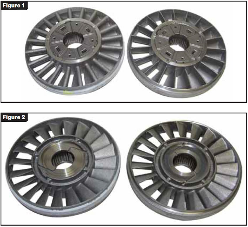
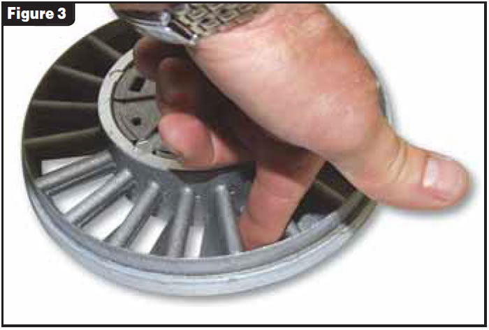
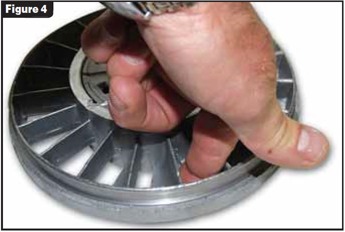
The exit angle on the two stators is also quite similar. One of the major differences between them is the number of vanes: the 144K-factor stator has 20 vanes and the 145K has 19. Another difference is the thickness of the leading edge of the vane. The 144K is thicker and rounded at its leading edge, and the 145K maintains its narrow thickness throughout the length of the vane. If you insert your finger into the opening between the vanes on both stators (see figures 3 and 4), it is easy to see how much larger the opening is on the 145K-factor stator.
With the larger windows on the 145K you would expect to see:
- Better torque multiplication
- Better coupling ability
- Lower stall and stall torque ratio, and, last but not least
- Less torque reversal.
A similar modification to the stock Cummins diesel stator to make it look more like the 145K-factor stator is very popular. This modification on the Cummins converter has produced gains of up to 30 horsepower on the dyno.
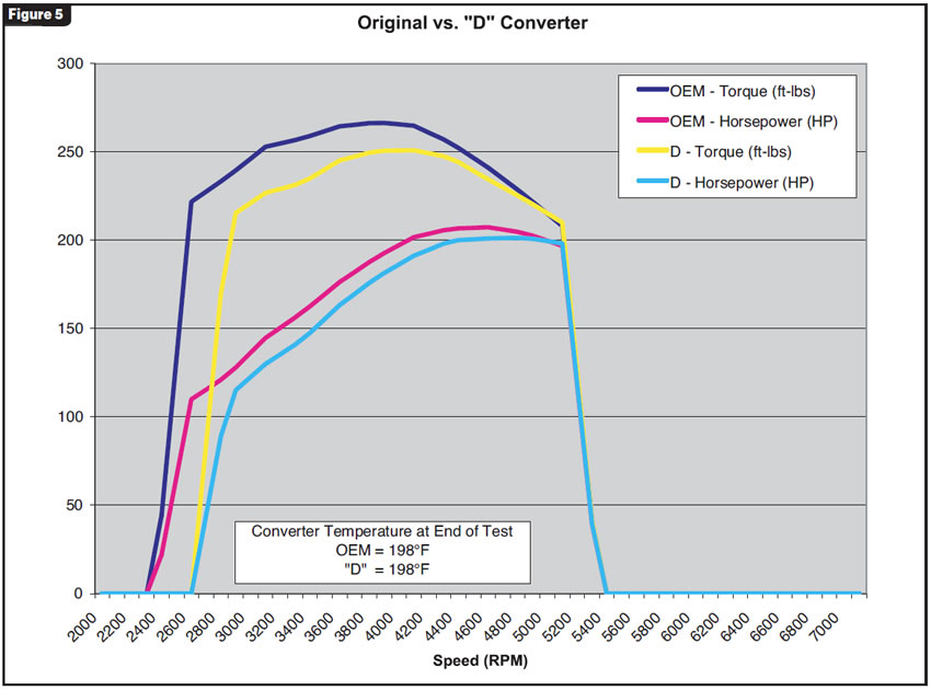
You would expect to see similar results when comparing the OEM converter with the modified D converter, especially considering the results of the A, B and C converter tests. But the modified D converter did not perform as expected. The overlay graph in Figure 5 shows the D converter having 300 rpm higher stall than the OEM, and sub-par performance levels like the higher-stall B and C converters.
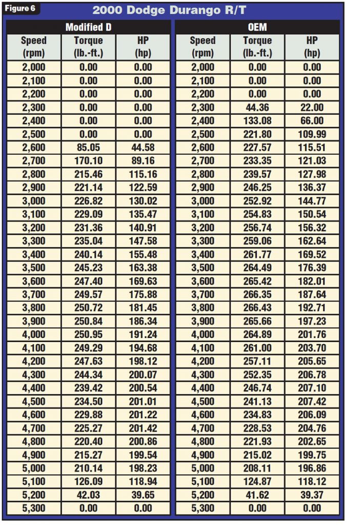
The line-by-line chart (see Figure 6) also backs this up. The higher the K-factor number, the higher stall the stator should have, but it is difficult to see why you would get higher stall from the 145K-factor stator. The answer can be seen in a side-by-side blade comparison after the outer rings have been removed from the stators (see Figure 7).
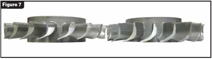
The leading edges of both stators are about the same distance from the turbine. They both have about the same blade angle, but the length of the blade is different. The 145K-factor stator on the right has a longer blade. This brings the blade closer to the impeller, raising the stall. Remember that modified converter A had material machined from the impeller side of the stator (increasing the distance between the stator and impeller), which lowered the stall. Decreasing the distance between the stator and impeller has a greater effect on raising the stall than the increased volume of flow has on lowering the stall. One positive note is that this method of raising the stall did not produce the elevated temperatures we saw in converters B and C.
It was obvious from all the evaluations that the test vehicle responded more favorably to a lower-stall converter than to any of the higher-stalls. The higher-stall converters also had some negative trade-offs – less fuel economy and elevated operating temperatures. Keep that in mind next time your customer asks for a high-stall converter.
The 145K stator was designed for vehicles with higher-output power plants than our test vehicle, and this led to some of the misleading results.
If you are forced to replace a 144K-factor stator with a 145K-factor stator, you can do this by machining 0.125 inch from the impeller side of the 145K to make it compatible.
Special thanks to Sean Boyle and Southern Illinois University for making this article possible.

Ed Lee is a Sonnax Technical Specialist who writes on issues of interest to torque-converter rebuilders. Sonnax supports the Torque Converter Rebuilders Association. Learn more about the group at www.tcraonline.com. ©2007 Sonnax Industries Inc.


