Torque Converter Tech Tips
- Author: Ed Lee
Part 1 in a four-part series on torque-converter modifications
When the vehicle manufacturers create their driveline packages, they have many issues to consider, such as fuel economy, performance and durability. In the torque-converter-rebuilding industry, many companies will make modifications to enhance the OEM torque converter for a specific vehicle combination. Some modifications are done to create better acceleration and others are done to improve towing capabilities and fuel economy.
However, when modifications are aimed toward specific applications, their use is somewhat limited. There are also some definite trade-offs to consider when modifying a converter: for example, increased operating temperature or loss of fuel economy.
The torque-converter industry is full of highly creative individuals who have come up with a large number of modifications. For the sake of this article, to determine which modifications create what results, we have picked four popular modifications for side-by-side, apples-to-apples evaluations. These evaluations were done to analyze some of the trade-offs.
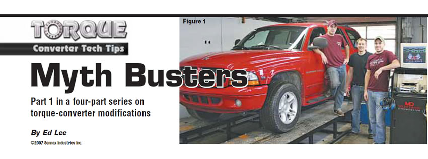
The evaluations were done on an MD-250 Mustang chassis dyno by Sean Boyle at Southern Illinois University. The evaluations were done as part of SIUC’s automatic-transmission course, which is a 10-week course covering theory of operation, rebuild and diagnosis of modern automatic transmissions. Three students – Jack Emberton, Ross Rohlman and Luke Davies – took part in the class project and are shown in Figure 1 along with the test vehicle.
The test vehicle was a stock 2000 Dodge Durango RT, equipped with a 5.9-liter gas engine and 46RE automatic transmission. The tests were standard wide-open-throttle (WOT) horsepower tests. The test started when the transmission oil temperature reached 160° F and was stopped when the vehicle speed reached 105 mph. The 105-mph speed allowed the engine to attain near-redline performance, and in every test the torque began to drop off by the end of the run. The converter temperature was measured by a pyrometer at the cooler line between the transmission outlet and the cooler inlet. The vehicle was locked in third gear (direct drive) and lockup was inhibited.
Five runs were done with each converter. All five runs were consecutive with about a 30-second time delay between runs. The five runs with the stock unmodified 144K-factor torque converter established the baselines for the evaluations. For testing purposes, the four modified converters were labeled A, B, C and D. (This article is about only the “A” converter. The “B,” “C” and “D” converters will be the subjects of the rest of this four-part series.)
As in most dyno tests, temperature affects the horsepower and torque readings. As the test vehicle warms up, the horsepower and torque readings will improve slightly with each run until they peak. They then will start to decline in a similar manner. Test 4 was used for evaluation purposes on all converters for uniform consistency.
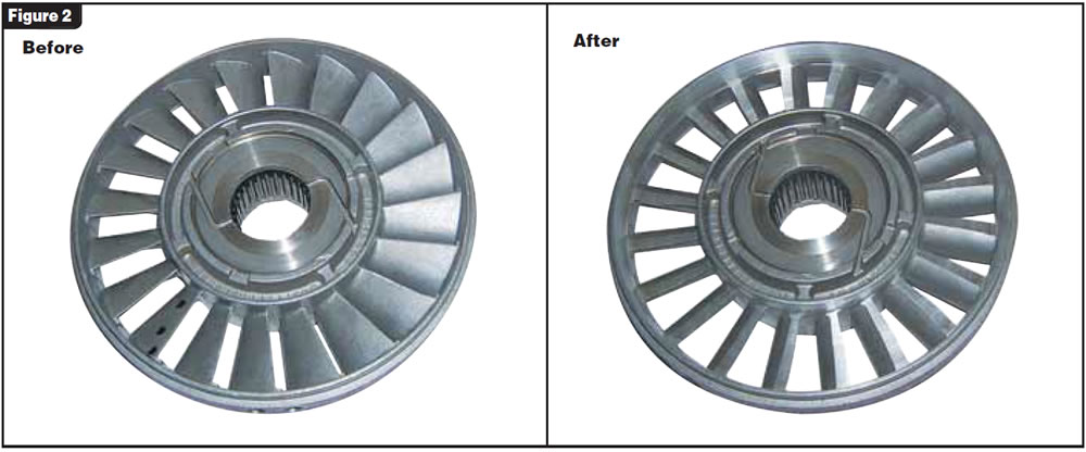
Converter “A” was modified by machining 0.250 inch from the impeller side of the stator. Figure 2 shows a comparison of the stock stator on the left and the modified version on the right. In the past, this modification was done to take advantage of the lower torque curve of the diesel and long-stroke gas engines. It also has been done to increase towing capabilities and enhance fuel economy.
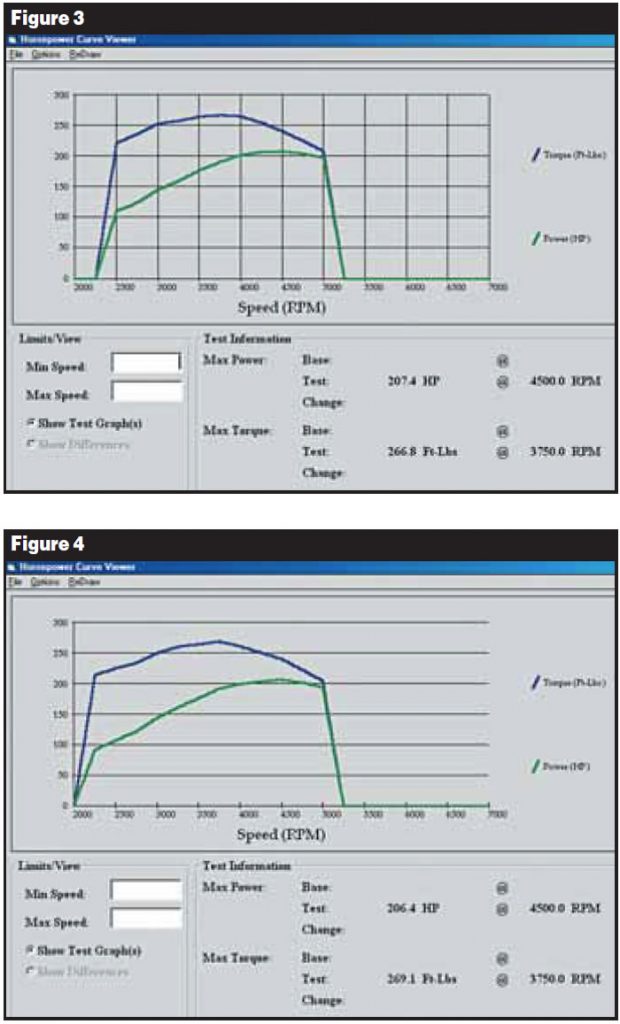
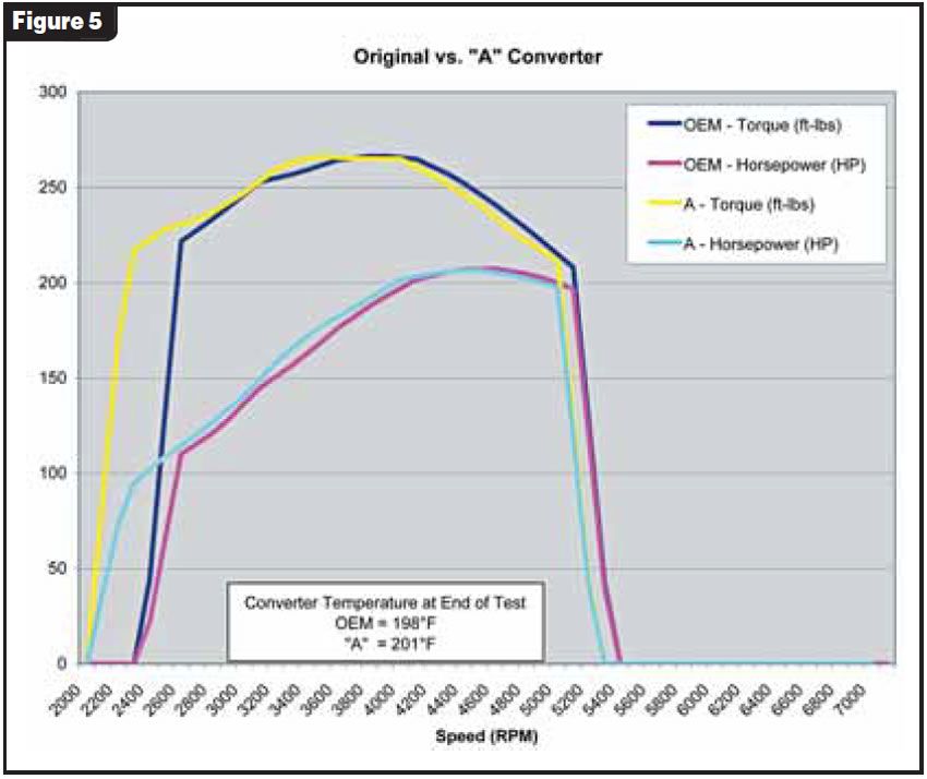
When you view the graphs of the original and modified “A” converter individually (see figures 3 and 4) it’s difficult to see much of a difference. But when you lay the modified “A” graph over the original converter graph (shown in Figure 5), you can see obvious differences. The first thing you notice is that the stall of the modified converter is lower because the horsepower and torque readings start at a lower speed (rpm). The readings start almost 400 rpm earlier on the modified converter. If you do a line-by-line comparison of the horsepower and torque readings at the same speed, the differences are even more dramatic (see Figure 6).
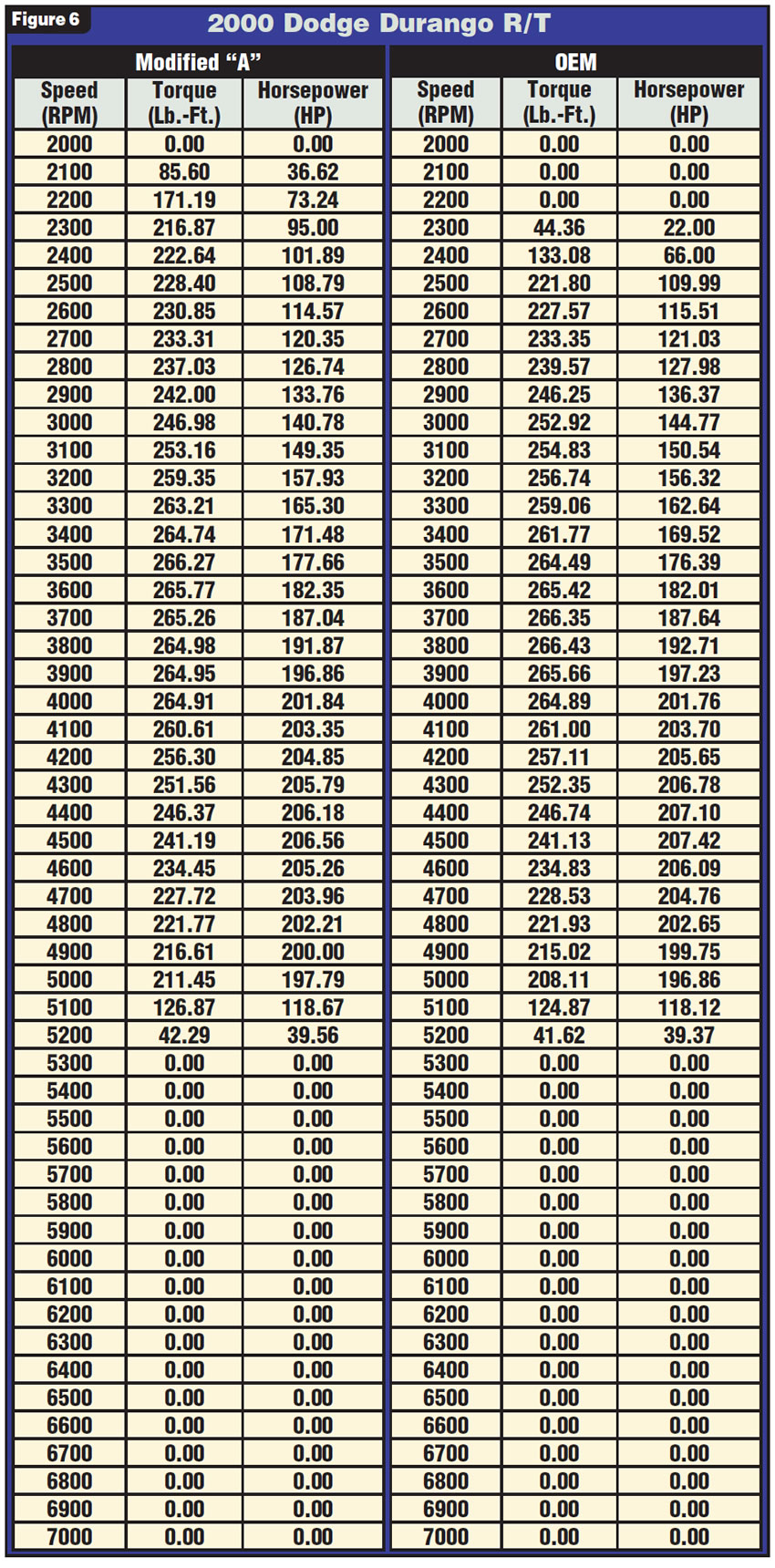
The difference is most noticeable at 2,300 and 2,400 rpm. At one point there is a gain of more than 70 horsepower and 150 lb.-ft. of torque between the modified converter and the stock converter. This is where you would notice the biggest improvement if you were towing with this vehicle. (Remember: This test was done with the 46RE locked in third gear and the TCC inhibited. Actual readings would be different if the transmissions were allowed to start in first gear and upshift.)
It is amazing how parallel the two runs are from 2,500 rpm to the end of the runs. There is seldom more than 1 or 2 horsepower or pound-feet of torque at each speed break, and there is only about 100 rpm difference at the point of peak performance between the two converters. From the test runs, the vehicle seemed to respond favorably to the lower stall, and you should see a rise in fuel economy with this modification.
Another favorable reading was the temperature. Any inefficiency in a torque converter usually causes a rise in temperature. It was a plus to see that after four runs the temperature in the modified converter was a modest 3°F higher than in the original converter (198°F to 201°F). After the fifth run, the temperatures were the same, 206°F.
When modifying a torque converter for enhanced performance, you must review many aspects of vehicle combinations. In the process of modifying a torque converter you need to be aware that improving one aspect of performance may reduce another. Decreasing stall may rob the vehicle’s acceleration performance, and increasing stall (depending on how it is done) can create more heat and inefficiency. In the evaluations of these four modified torque converters, you can use hard facts to determine whether the trade-offs are worthwhile for your application.
Next month: How an increase in stall can affect vehicle performance.
Special thanks to Sean Boyle and his class at Southern Illinois University for their help in compiling this information.

Ed Lee is a Sonnax Technical Specialist who writes on issues of interest to torque converter rebuilders. Sonnax supports the Torque Converter Rebuilders Association. Learn more about the group at www.tcraonline.com. ©2007 Sonnax Industries Inc.


