Torque Converter Tech Tips
- Author: Ed Lee
The mystery
A 2003 Ford F-350 4X4 was brought to a transmission shop in Eugene, Ore. The customer complaint was an intermittent P0741 code. The code did not seem to occur when the vehicle was driven locally but happened every time it was taken on a longer trip. The customer also noticed that the code would set whenever any additional load was placed on the vehicle. The additional loads included traveling in hilly terrain or pulling a trailer.
The vehicle’s transmission had been rebuilt at the same transmission shop about a year earlier, and a rebuilt torque converter had been installed at that time. During the transmission-rebuild procedure a few mild performance-enhancing modifications were added, but other than that it was a basic overhaul. The customer said the lockup worked fine for about 300 miles but then was too soft. The soft lockup feel continued until the present P0741 code issue. A scan check did not find any additional codes, and a road test with the scan tool showed that there was sufficient TCC slip to set the code. All the routine “in-vehicle” checks were performed, and the cause of the problem was believed to be the converter.
The transmission shop had changed hands during the past year, but the new owner was familiar with the customer and was willing to stand by the warranty. The transmission and converter were removed from the vehicle. The new shop owner had changed his torque-converter supplier since acquiring the shop, so the torque converter did not go back to the original rebuilder. The converter was sent to the shop’s new supplier, Oregon Converter Co.
Ken Cluck, the production manager at Oregon Converters, had the converter cut apart. The end-play and clutch-release clearances were within specifications, and the clutch did not look as if it had been slipping. Ken was convinced that the TCC slip problem was originating outside of the converter, but as an extra measure of insurance a new clutch piston was installed.
The transmission and converter were put back into the vehicle and the vehicle was road tested. The extensive road test covered all types of terrain, including several hilly areas. Since the TCC slip condition did not return during the road test, Ken believed that the problem had been resolved, even though he had not found anything conclusive inside the converter.

The vehicle was returned to the customer, and again it performed well for about 300 miles. After 300 miles the TCC apply feel again began to soften. By the time the vehicle was returned to the transmission shop, the data stream was showing enough TCC slip that the return of the P0741 code was inevitable. Since the converter reacted in much the same way as it did after the first rebuild, Ken believed he needed to take a closer look.
The answer
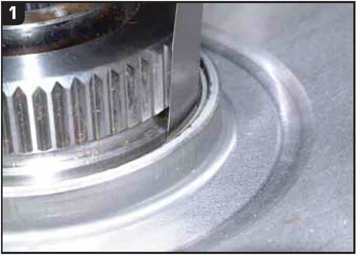
Closer scrutiny of the converter did reveal something that was missed on the first inspection. The bushing in the inside-diameter bore of the TCC piston looked like new, but there seemed to be more-than-normal clearance between the bushing and turbine hub. The OE clearance for this area, when the converter is new, is about 0.0015-0.002 inch. As a general rule of inspection, for a unit that has been in the field: If a 0.002-inch feeler gauge fits between the bushing in the TCC piston and the turbine hub, the bushing is good. If a 0.003-inch feeler gauge is a tight fit, the bushing is marginal but will work. If a 0.004-inch or larger feeler gauge will fit, the bushing must be replaced. Ken found that he could fit a 0.007-inch feeler gauge between the bushing and turbine hub on the problem converter (Figure 1).
Since there is no additional O-ring or lathe-cut seal between the piston and turbine hub, the clearance between the bushing and turbine hub acts as an orifice. Almost five times as much oil was leaking past this area than should have been, because of the excess clearance. Ken went back and checked the piston he had replaced the first time around. He found that an 0.011-inch feeler gauge would fit between the piston bushing and turbine hub. This extra clearance with either piston would explain the P0741 code, but why was the clearance there?
The answer to the answer
When Oregon Converter Co. rebuilt the converter, it reused the turbine hub, which looked like new. The turbine hub had been replaced by the original rebuilder. Unfortunately, the surface finish on the turbine hub, where the bushing in the inside diameter of the TCC piston rides, was rough enough to wear the bushing out prematurely.
The surface finish for this area should be in the range of 10 to 20 RA. The surface finish on this turbine hub exceeded the profilometer’s maximum reading of 200 RA, and a good guess would put this turbine hub’s finish at about 300 RA. The finish was rough enough to catch a fingernail but was difficult to detect visually. In fact, the outside diameter of the problem turbine hub measured the same as that of an OE hub and felt smooth when you ran your finger around the circumference.
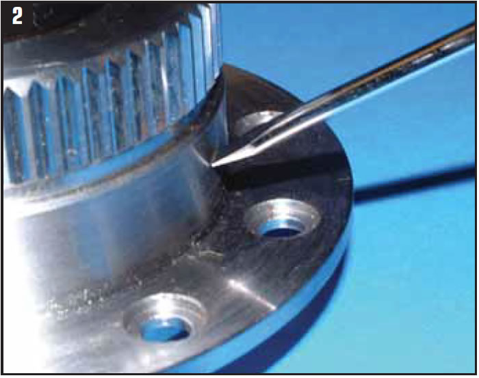
If you do not have a profilometer, the best method of checking for smoothness is to run a fingernail across the surface, or place your pocket screwdriver at a 45° angle to the surface and push it across the surface (Figure 2).
Most converters rely on an O-ring or lathe-cut seal to control oil flow between the turbine hub and TCC piston. Because the 4R100 and 5R110 converters do not have any seal in this area, it becomes critical that this clearance be measured during the rebuild process.
Special thanks to Ken Cluck, production manager at Oregon Converters, for sharing his story and information.
Ed Lee is a Sonnax Technical Specialist who writes on issues of interest to torque converter rebuilders. Sonnax supports the Torque Converter Rebuilders Association. Learn more about the group at www.tcraonline.com.


