Mystery Noise in the ZF 5HP19/24 - Transmission Digest

Mystery Noise in the ZF 5HP19/24

It’s not uncommon to hear customer complaints about a noise coming from a vehicle equipped with either a ZF 5HP19 or ZF 5HP24 transmission. The noise is most often described as a squealing or squawking sound and can be heard when the customer lifts his foot off the accelerator pedal. The sound is similar to that of a bad transmission pump and can be heard in any forward range but is most noticeable in first or second gear.

Mystery Noise in the ZF 5HP19/24

Torque Converter Tech Tips

Author: Ed Lee

Torque Converter Tech Tips

  • Author: Ed Lee

It’s not uncommon to hear customer complaints about a noise coming from a vehicle equipped with either a ZF 5HP19 or ZF 5HP24 transmission. The noise is most often described as a squealing or squawking sound and can be heard when the customer lifts his foot off the accelerator pedal. The sound is similar to that of a bad transmission pump and can be heard in any forward range but is most noticeable in first or second gear.

In the early 1980s, transmission technicians had a very similar noise issue with GM’s 700-R4 transmissions. The noise sounded the same but was heard under different conditions. The noise in the 700-R4 became audible when the vehicle was accelerating heavily. The technicians were able to isolate the noise by operating the vehicle in the D or 3 range; when the transmission was in those ranges the noise disappeared. Placing the transmission into the D or 3 range prevented the transmission from advancing past 3rd gear, but, more important, it applied the overrun clutch for engine braking. Since the overrun clutch holds the same driving component that is held by the forward sprag, it was safe to assume that the noise was coming from the forward sprag.

Unfortunately, the noise in the ZF 5HP19 and 24 transmissions was much more difficult to diagnose, even though it also was eventually traced to a sprag. The sprag that was causing the noise couldn’t be isolated because it was in the torque converter, not the transmission. The only component that the sprag held was the stator. Eventually, the noisy sprag was found by a process of elimination.

Frank Kuperman, from Redline Torque Converters in Phoenix, recognized the urgency of customer complaints about the noise because he knew that the R&R time for the Audi ZF 5HP24 transmission was more than 16 hours. Frank reasoned that the noise occurred when the customer lifted his foot off the accelerator, and this was the same time that the sprag in the stator started to freewheel. Since the sprag’s inner race is splined to the stator support and does not rotate, the noise had to be coming from the contact point between the sprag and the inner race.

Figure 1 shows a new inner race. Figure 2 shows a used race that does not make any noise. Figure 3 shows a used race that is noisy. There is very little visual difference between the quiet and noisy inner races. The best way to check the surface of the race for conformity is to use your fingernail or a scribe. No part of the race should catch on your fingernail or scribe.

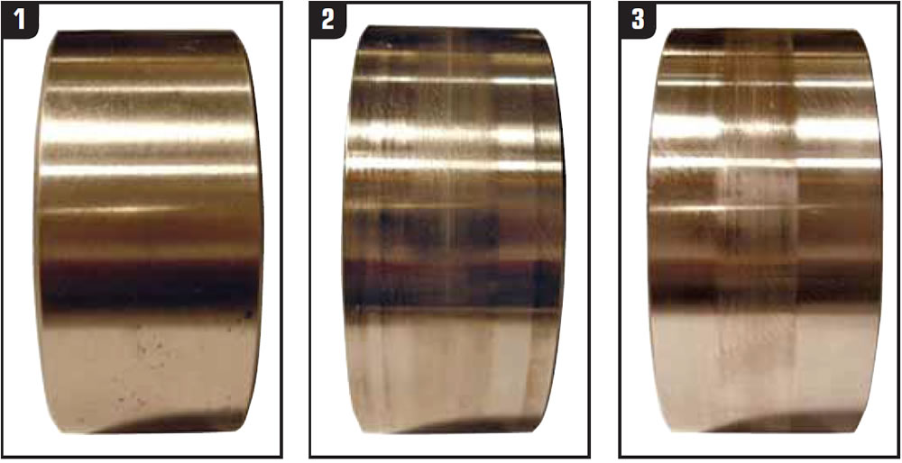
The traditional method of checking the sprag’s ability to function will tell you only that the sprag will lock and freewheel. This method will not identify any noise issues, so take the extra time and visually check all sprags.

Special thanks to Frank Kuperman of Redline Torque Converters in Phoenix for his help in solving this mystery.

Ed Lee is a Sonnax Technical Specialist who writes on issues of interest to torque converter rebuilders. Sonnax supports the Torque Converter Rebuilders Association. Learn more about the group at www.tcraonline.com. ©2008 Sonnax Industries Inc.

You May Also Like

Sherlock Holmes Approach to an AB60 No-Move Situation

The effectiveness in diagnosing automatic transmission malfunctions is an art form. Although there are similarities among the wide varieties of transmissions on the road, each transmission has its own peculiarities. Aside from having mechanical, hydraulic, and electrical hardware systems to contend with, software/programming issues and various vehicle platforms make diagnostics much more difficult.  Using scopes provides

ab60

The effectiveness in diagnosing automatic transmission malfunctions is an art form. Although there are similarities among the wide varieties of transmissions on the road, each transmission has its own peculiarities. Aside from having mechanical, hydraulic, and electrical hardware systems to contend with, software/programming issues and various vehicle platforms make diagnostics much more difficult. 

GM 6T40 Pump Identification Guide

The 6T40 was introduced in 2008 for General Motors front-wheel-drive cars in the Chevrolet Malibu and has gone through several changes throughout its three generations, specifically in the pump area. The 6T40 is closely related to the more lightweight 6T30 and the heavier duty 6T45 and 6T50. Generation one started phasing out during the 2012

Seeing the Forest AND the Trees

They say that the proverbial phrase “I couldn’t see the forest for the trees” means that a person or organization cannot see the big picture because it focuses too much on the details. Related Articles – 4L60E Harsh 1-2 Shift – TASC Force Tips: Diagnosing 8L45 & 8L90 Shift Complaints – TASC Force Tips: Hydraulics

The Manifold Pipeway

The Honda six-speed transmission has been on the bench of many specialty shops for one reason or another (figure 1). But, for those of you who have yet to lay your hands on one, mounted on the upper side of the unit is one of the largest, if not the largest solenoid and pressure switch

8L90 Vacuum Testing

Below are the diagrams for vacuum testing GM 8L90 transmissions. Note: OE valves are shown in rest position and should be tested in rest position unless otherwise indicated. Test locations are pointed to with an arrow. Springs are not shown for visual clarity. A low vacuum reading indicates wear. For specific vacuum test information, refer

Other Posts

Critical Wear Areas & Vacuum Test Locations for FORD 6R80/6R100

Note: OE valves are shown in rest position and should be tested in rest position unless otherwise indicated. Test locations are noted with an arrow. Springs are not shown for visual clarity. Low vacuum reading indicates wear. For specific vacuum test information, visit www.sonnax.com. Related Articles – Hydraulics Fundamentals: Shift & Relay Valves – Another

Hydraulics Fundamentals: Shift & Relay Valves

Shift valves and relay valves share a lot of the same duties. This article is one of a series by Sonnax exploring how valves and hydraulic circuits work and what results when they quit functioning correctly.

Another 62TE ‘No-Move’ Possibility

Most seasoned techs have several quick diagnostic steps they take when faced with a transmission malfunction. The type of problem and transmission determines which steps to take. For example, a “no-move” condition. Related Articles – Ford 8F35 maintenance tips: Planetary failure and no-pressure conditions – Don’t fear customer complaints about CVTs – Shift Pointers: A Chrysler

Hydraulics Fundamentals: Clutch Regulator Valves

Knowing how these circuits work and the slightly different variations that the manufacturers utilize should pinpoint any valve body-related issues