R&R Tech
- Author: Dana Deeke
- Subject Matter: 2010 Dodge Journey AWD, 62TE
- Issue: Loose pin fit for Connector C101
Make sure you verify the presence of voltage where it needs to be
A customer brought in a 2010 Dodge Journey AWD with the high-output 3.5-liter V6 engine and the 62TE automatic transmission. With a little more than 83,000 miles on the odometer, the complaint was for no upshifts and stuck in 3rd-gear failsafe mode. This concern had started out as an intermittent issue but now had become more regular.
The preliminary visual inspection was performed and a diagnostic tool was connected to scan for codes in the electronic systems. The fluid level was noted as being a little low and there was a slight transmission cooler-line leak. The condition of the fluid was still red in color. The scan tool pulled several DTCs as follows: P0765 (underdrive solenoid circuit), P0750 (low/reverse solenoid circuit), P0562 (battery system voltage low), and P0755 (2-4 solenoid circuit). There were also some body-control codes set: B21A1 (ECU reset) and B25AC (door module not calibrated). We try to make sure we always scan all systems when scanning for codes rather than just concentrating on the engine and transmission; it is a practice that has served us well over the years.
As you can see, not only were there codes relating to the transmission, there were body-control codes also. Sometimes these other codes can be a great clue to a problem in another system. After recording the code data, they were cleared and the vehicle was road tested to check the operation. After a very short time the Journey went into failsafe mode again, but this time it had only set P0562. After doing a little research I found the set criteria and the possible causes for this code (Figure 1).
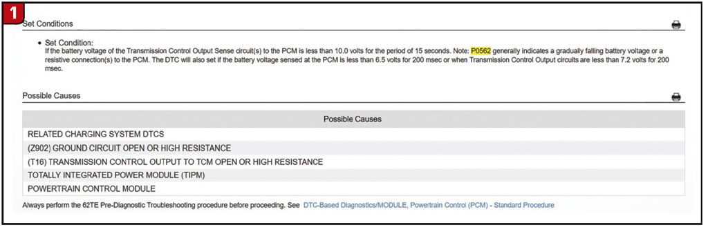
As shown, there are multiple causes for this code. A common cause for this code is a gradually failing battery or alternator with voltage that falls below 10.0 volts for 15 seconds. One of the things we do as part of our routine checkout is a battery and charging system test. Today’s vehicles are very sensitive to battery voltage changes, especially low voltage, and excessive AC ripple. We have seen many issues caused by excessive alternator ripple, ranging everything from codes to erratic speedometer operation and erratic shifting.
We also checked the grounds for corrosion and that they were tight. Once in a while we can get wrapped up in finding a complicated electrical issue and overlook the simple things, like poor ground paths. In this case everything checked out so we moved on to the next step: a battery and charging system test.
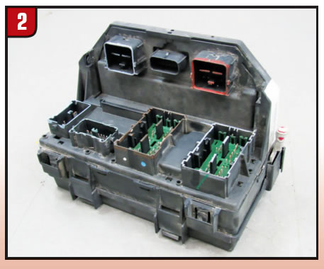
For these tests we use a Midtronics battery and charging system tester. It showed that the battery was in good health and that the starting and charging systems were operating as they should, without any excessive ripple. Feeling pretty confident in the battery and charging system integrity, we continued our search. Since the diagnostic information indicated that the code would set if the PCM has commanded the TIPM (totally integrated power module) to energize the transmission control output, and we did not see the expected voltage on the transmission control output sense circuit, we went to the TIPM located under the hood on the driver’s side of the vehicle (Figure 2).

We used the wiring diagram for the subject vehicle to determine which connector on the TIPM was correct for testing. The back of the TIPM was accessed to make it easier for testing (Figure 3).
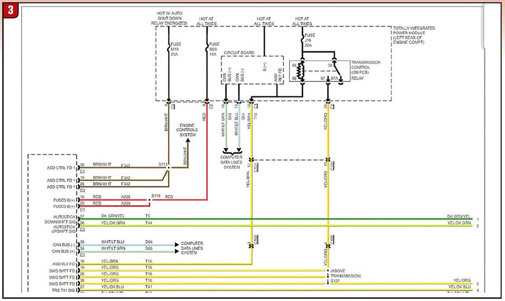
We are focusing on circuit T16: the transmission control output circuit. This circuit branches off in three legs from the PCM. There is a connector C105 and C101 between the PCM and the TIPM. I wanted to verify that the TIPM was energizing the transmission control output. This happens on the yellow/orange wire from the transmission control relay in the TIPM. We used the Snap-on scope to monitor power and hopefully catch any quick dropouts in power. With key on, engine running, I was able to confirm that the TIPM was in fact sending out the signal on T16.
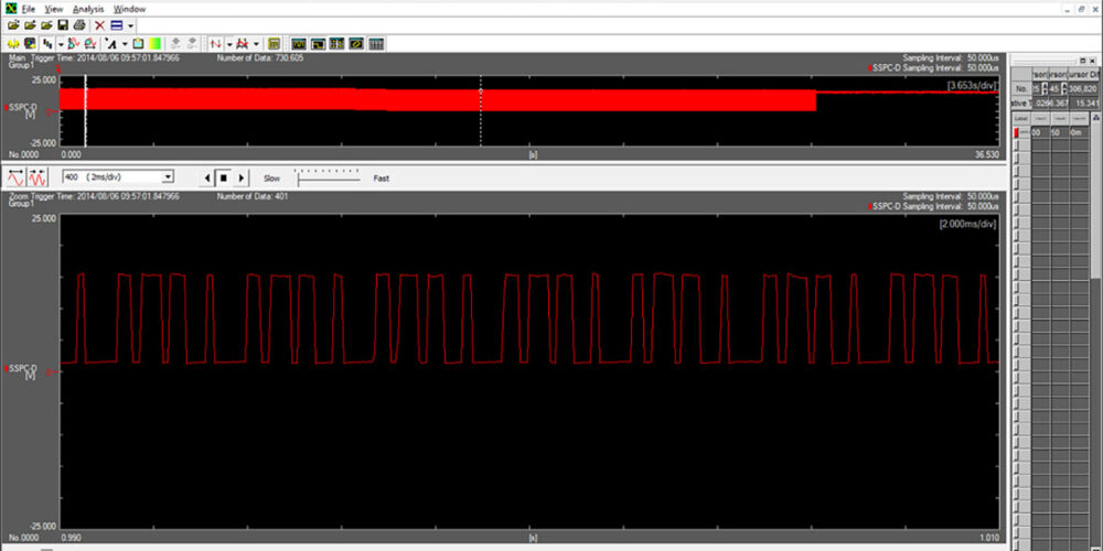
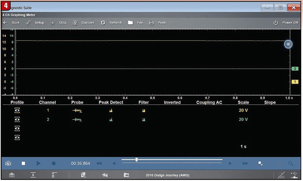
I left the scope connected at that location and added another channel to monitor voltage on T16 at the transmission solenoid. After doing several cycles of the key and starting the engine each time, we eventually lost voltage at the transmission solenoid. Since we had both channels going at the same time, we saw that power remained constant coming out of the TIPM. Channel 1 is the TIPM and channel 2 is the transmission solenoid pack (Figure 4).
Having verified that the PCM was sending the command, and that the TIPM was receiving the command then sending the signal output, it was apparent that the signal was not reaching the transmission solenoid assembly. This led us to looking at the wiring and connectors that were left in the circuit. With the scope still attached at the previous points and the engine running, we started moving wires while watching for any voltage changes. At this point the vehicle had come out of limp and of course we had power at both points that the scope was hooked to. After a few minutes of run time while wiggling wires, the vehicle again went to failsafe mode and set the P0562 code.
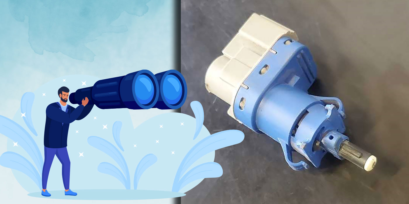
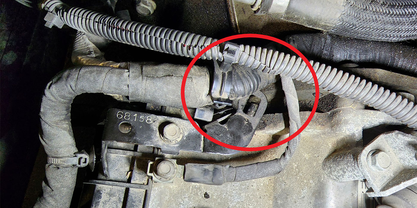
After working our way along the wire loom we arrived at a connector that when moved, we could duplicate the power loss repeatedly. Connector C101 is found near the PCM on the top of the transmission (Figure 5).
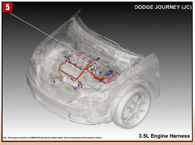
The connector was taken apart to check for damage or corrosion on the pins. The connector appeared to be sealed with no damage to the weather pack seal. No corrosion was found. However, the pin fit from male to female was not very tight. Once we isolated the area of the problem, a new wire connection was temporarily made to go around the loose pin at C101. The vehicle was tested multiple times and no more issues were noted. A complete system scan showed no codes present. It has been out on the road for several months now and after checking in with the owner it has worked without incident.
Since the time we had diagnosed and repaired this vehicle, we have had another come in that had the same code and symptoms. It was found to have the same connection problem at the same connector. If you have one of these vehicles come into your shop with this concern, make sure you verify the presence of voltage where it needs to be, and if there is a loss, where it is being lost. While these do have some common problems with TIPM failures as well as PCM issues, take the time to isolate the problem and you may just find a connector issue like I did. I am sure there are other Chrysler vehicles that may have a similar setup to this Journey, so it would certainly be worth your time to take a look.