Torque Converter Tech Tips
- Subject: Finding the cause of cold stall and TCC shudder
- Unit: 722.6
- Vehicle Application: Mercedes ML430, E320 AWD, 2004 C230
- Essential Reading: Rebuilder, Diagnostician
- Author: Ed Lee
For several years, technicians have been trying to solve the mysterious cold-stall issue in vehicles equipped with Mercedes 722.6 transmissions. When the problem was first identified, it was thought to be associated with aftermarket components. At that time, no one had seen the problem in a vehicle that still had only original equipment.
For that reason, most early efforts to solve this cold-stall problem were focused on the replacement friction material that was used in the rebuild process. Every conceivable kind of friction material with both smooth and grooved surfaces was tried, and most had some limited successes. Rebuilders would use the friction material that seemed to work the best for them, but no material proved to be foolproof.
As things turned out, the aftermarket was not alone in the struggle.
The OEM friction-material choice evolved during this same period, and even for them nothing proved 100% successful. When technicians started seeing vehicles with nothing but original equipment experiencing the same cold-stall condition, they turned their focus toward wear issues.
Technicians began to identify worn seals, worn bores and cross-leak issues. The first seals to come under scrutiny were the TCC piston seals. The OEM seals were loose fitting, and the aftermarket responded with snugger, better-fitting seals. Many of the early shudder issues were fixed by just replacing these seals, but some issues still remained. These unresolved issues made technicians look further into the TCC apply circuit.
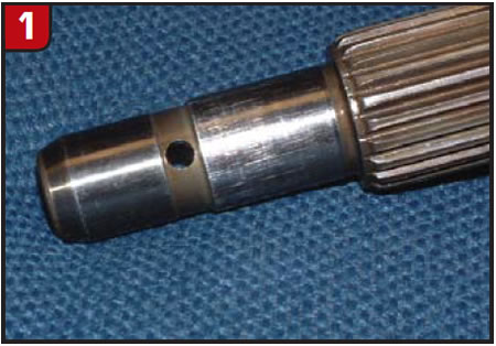
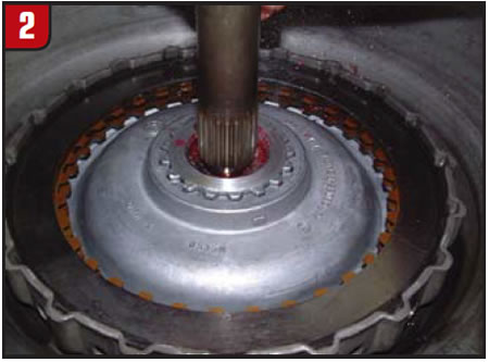
The Mercedes 722.6 converter uses a clutch pack to provide TCC clamping force and a three-path converter-oil circuit. One path is for converter charge oil to enter the converter, and another is for lube oil to exit the converter. The third circuit is used to provide TCC apply-oil pressure during lockup or to allow apply-circuit oil pressure to exhaust when the TCC is released. The apply oil travels through the input shaft and exits between the smaller and larger diameters of the smooth areas at the end of the shaft (Figure 1).
The oil that exits the shaft travels into the aluminum tower that is part of the cover. The inside-diameter seal of the TCC piston seals on the outside diameter of this tower. The smaller and larger diameters of the input shaft use different methods of sealing between the shaft and the mating surfaces of the cover tower. The smaller diameter uses an O-ring or lathe-cut seal, while the larger diameter relies on an interference fit. The cover tower rotates at engine speed. The input-shaft speed can range from zero at a standstill to the same as engine speed during full lockup.

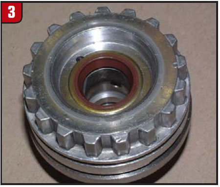
The potential speed difference between these mating parts makes you wonder why either the O-ring/lathe-cut seal or the interference-fit options were chosen for this application in the first place. A radial lip seal would seem to have been a much better choice. Despite the possible poor choice of seals, many technicians have reported successfully fixing both cold-stall and TCC-shudder problems by restoring the integrity of these seals. The leak visible in Figure 2 was a result of bore wear at the interference fit of the tower.
One mating surface is the larger diameter of the input shaft, and it measured 0.660 inch. The other mating surface, the cover-tower bore diameter, measured 0.683 inch. The bore diameter of a good OEM tower measures 0.662 inch. The difference between the 0.002-inch factory-intended clearance and the 0.021-inch clearance of the worn bore pictured here resulted in a leak of 7.5 gallons per minute (GPM), not to mention both cold-stall and TCC-shudder issues. This issue was resolved by removing the O-ring/lathe-cut seal, blocking the lube-bypass passage and installing a radial lip seal (Figure 3).
Continuing downstream in the TCC apply circuit, the next area for a possible leak or cross leak is the sealing rings for the turbine (input) shaft. Art Landeck from Consumer Transmission in Poughkeepsie, N.Y., reports fixing the cold-stall conditions in two different vehicles by replacing the early-model, dark-gray scarf-cut turbine-shaft rings with the late-model, tan interlock rings.
The first vehicle was an ML430 that came to Art’s shop with a gear-train issue. After the repair was completed, the vehicle would stall the engine on cold startup in either forward or reverse. After he replaced several valve bodies and solenoids, the problem was unchanged. Art pulled the unit and replaced the stator support and installed the late-model turbine-shaft rings. This solved the problem.
The second vehicle was an E320 AWD with 70,000 miles on the odometer. This vehicle’s only complaint was a cold stall. To verify the fix of the first vehicle, Art only replaced the turbine-shaft sealing rings with the late-model rings.
If you follow the TCC apply circuit all the way to the valve body, you will find several valves that have a potential to leak or cross-leak: the main pressure-regulator valve, the TCC damper valve and the TCC control valve (Mercedes calls this valve the torque-converter lockup-clutch control valve). All three of these valves deserve close scrutiny. ATSG’s Wayne Colonna recently wrote an article about how bore wear at the lubrication-pressure regulator valve will cause higher-than-normal charge pressure (722.6/NAG 1, Transmission Digest, January 2010). Now you can add a fourth valve to your inspection routine.
Searching for the root cause
Wayne Russell of Russell Auto Inc. in Manchester, N.H., had a rare opportunity to find the root cause of the cold-stall problem. Wayne’s situation was unique for three reasons: 1) The 2004 C230 was an untouched, low-mileage (68,509 miles) vehicle with only a cold-stall complaint, 2) Wayne was able to successively try every available fix that was known at this time (sequence to follow), and 3) he had a tolerant, accommodating customer (which can be rare in this industry).
When the C230 arrived at Wayne’s shop, the first change was to replace the lockup solenoid. The second change was to install the first of two rebuilt valve bodies he would eventually try. On the third day the unit was pulled for the first time. The stator support was inspected and found to be in perfect condition, the turbine-shaft sealing rings were replaced with the newest version, and the torque converter was replaced with a special unit built by Rick Morris at Professional Converters in Marcy, N.Y. The converter had the latest clutches, and a radial lip seal was added where the input shaft is inserted into the cover tower (zero leakage).
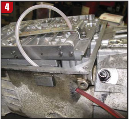
On the fourth day the TCC control valve was blocked in the TCC-release position. The next change was to bypass the cooler lines and cooler. Special fittings were made, and the cooler lines were looped so the fluid flowed out of one cooler fitting and back into the other. Up to this point there had been no change to the cold-stall condition. Wayne wanted a test to verify whether cross-leak oil was applying the TCC piston. With Bob Warnke’s help, Wayne tapped into the exhaust passage at the TCC control valve and routed a hose from that passage to the outside of the transmission case. With the valve in the release position, this circuit is directly connected to the TCC apply-oil circuit (Figure 4).
A steady stream of fluid would prove that the TCC piston was being hydraulically applied by cross-leak oil. No steady stream of oil flowed from the hose, so the test did not prove what was expected, but Wayne learned one very important piece of information. As fate would have it, the clear plastic hose that exited the transmission was run vertically upward. This made the hose act like a standpipe, and when the engine was started the fluid rose about a foot up the tube and stayed at that position. This information proved to be critical.
To understand this problem you need to remember two characteristics of the 722.6 TCC design. In a typical single-TCC-piston setup, oil behind the piston holds the piston off the cover when it is in TCC release. In the 722.6 clutch-pack system, apply oil is routed between the cover and the piston on its way to applying the clutch. So first, remember that oil behind the piston, in this instance, is for TCC apply. Second, remember that there is no dedicated release-oil pressure sent in to keep the clutch from dragging. Release is accomplished by exhausting the apply circuit, allowing TCC charge-oil pressure to move the piston to the release position, squeezing the apply oil out of the cavity between the piston and the cover.
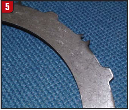
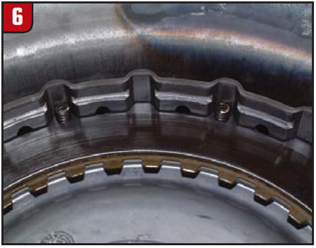
The oil rise in the exhaust-circuit tube showed that there was a pressure rise in the TCC apply circuit when the engine was started. More specifically, it showed that residual oil was trapped behind the piston and that when the engine was started centrifugal force was causing the piston to apply (as well as pushing oil farther up the tube.) If no residual oil were trapped behind the piston, the problem would not exist. Lacking any viable checkball or hydraulic option to purge the residual oil, Wayne tried a mechanical option. The middle steel plate in the clutch pack was modified by notching 10 of the 20 OD lugs to allow for spring clearance (Figure 5).
Ten springs were then added to serve as piston return springs (Figure 6) and – ta-da! – THE VEHICLE WORKED PERFECTLY!
This repair has since been done on other 722.6 converters, and most customers have reported that their vehicles have never worked as well. All the tugging, dragging feeling that was accepted as normal was gone. Even the chugging on downshift was no longer felt.
What was learned?
- Friction material does not play as big a part in cold-stall problems as originally thought.
- Circuit integrity is much more important than originally thought, because leaks and cross leaks allow more residual oil to remain behind the piston.
- Too much time and effort has been wasted by focusing on the clutch-pack side of the TCC piston. One can only imagine how much more time and effort could have been spent if Wayne Russell had not tried his simple test.
Ed Lee is a Sonnax technical specialist who writes on issues of interest to torque-converter rebuilders.
Sonnax supports the Torque Converter Rebuilders Association. Learn more about the group at www.tcraonline.com.
©Sonnax 2010