Technically Speaking: Part 1
- Author: Wayne Colonna, Technical Editor
- Subject Matter: Spark plug controlled compression ignition engine
- Issue: Solenoids
The progressive development of Mazda’s “SkyActiv®” engine and transmission has resulted in an engine that should be available in 2019 called the “SkyActiv-X.” The name SkyActiv given to this drivetrain reflects their back-casting developing method. They started with what they wanted to achieve regardless of how impossible it may seem, and work their way backwards to identify what made that goal seem impossible. Their goal was high in the “Sky” when they began this project. The first generation was “SkyActiv-G” which made its first appearance in 2012. The SkyActiv-Drive 6-speed automatic transmission mated to this engine provides fluid shifts along with quick, steady acceleration.
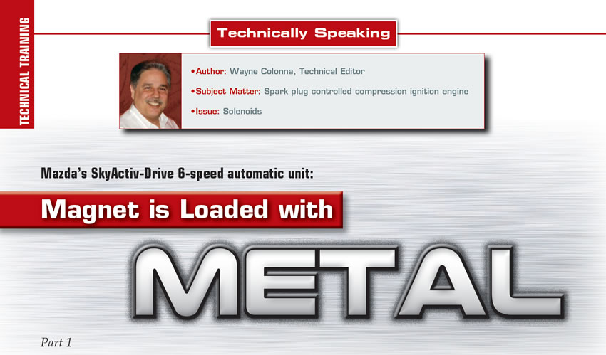
The newest SkyActiv-X engine coming out soon achieved this “sky high goal.” This engine is a Spark Plug Controlled Compression Ignition Engine (SPCCI) offering outstanding power, acceleration and environmental performance by combining the attributes of both spark and compression ignition. The SkyActiv-Drive 6-speed automatic transmission known as the FW6A-EL transmission (Figure 1) continues to be part of the drivetrain. With this transmission being on the road as early as 2012, it has not generated too many calls on ATSG’s technical help line. It may very well be a sleeper as the unit we obtained to use in our 2019 seminar and a couple of Transmission Digest articles has definite problems. Peeling this transmission apart to see what kind of damage occurred will give us the opportunity to get familiar with the unit.
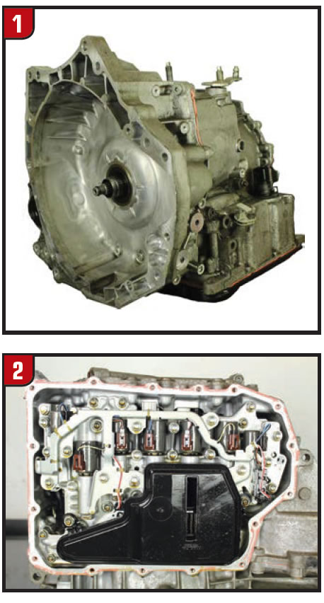
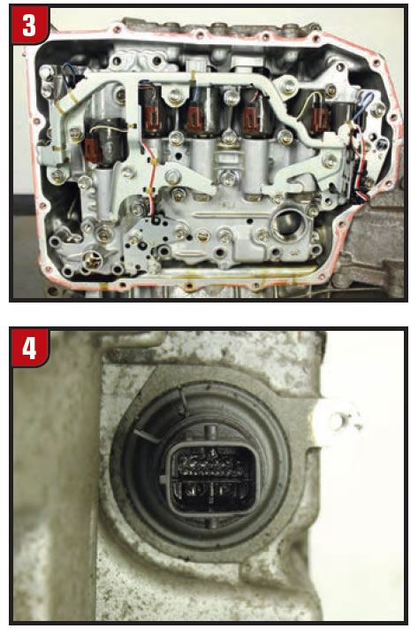
With the pan and filter removed (figures 2 and 3), a total of seven solenoids, two pressure switch manifolds and a range sensor come into view. Wire ties secure the wiring harness to a metal rail, which also blocks each of the solenoid’s retaining pin.
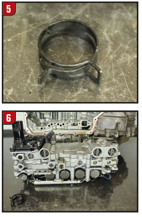
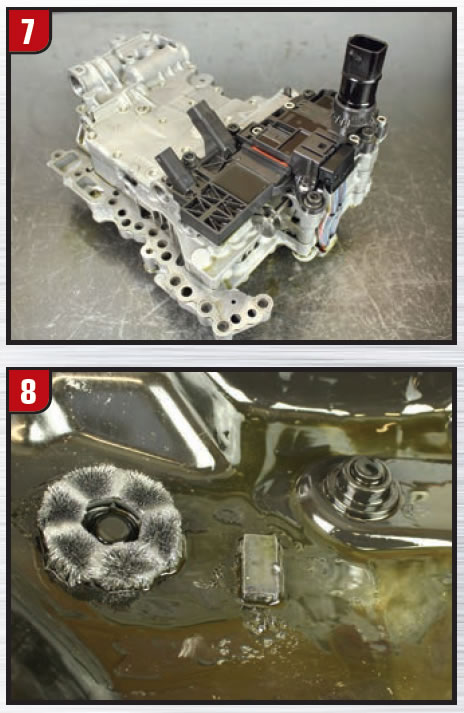
To remove the valve body assembly from the transmission, a hose type clamp around the pass through connector must first be removed (figures 4 and 5). The pass-through connector contains 14 pins leading you to believe the TCM is external. Not with this transmission. Once the valve body is removed (figure 6), The TCM can be found on the upper side of the valve body as seen in Figure 7.

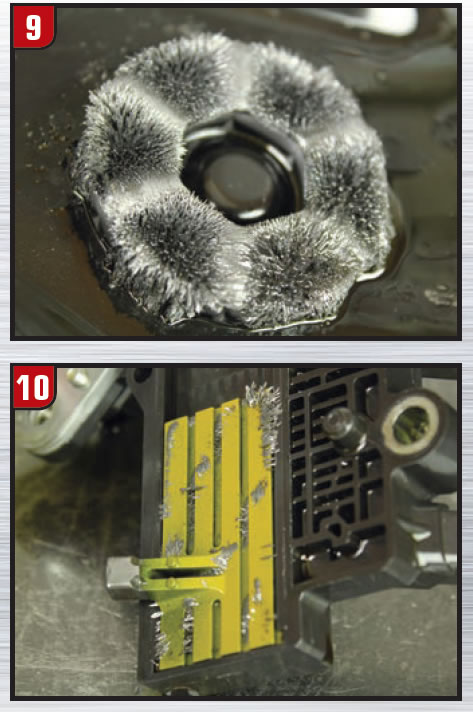
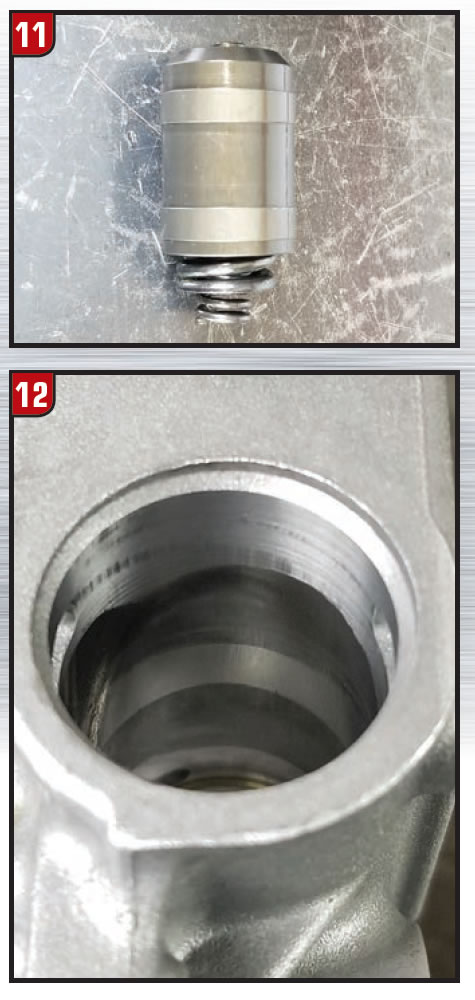
Looking at the inside of the pan (Figure 8), the magnet reveals a definite problem is present with this transmission. The magnet is loaded with metal (Figure 9). Metal like this causes many issues. Two of them are obvious: The magnet pad on the transmission range sensor attracts this metal causing range sensor codes (Figure 10); the magnet pad also causes the fluid to be an abrasive causing bore wear with moving valve and accumulators (figures 11 and 12).
With the metal wiring harness protector removed from the valve body, the solenoid retaining pins come out easily with a magnet allowing the solenoids to be removed from the housing (Figure 13). Identifying the solenoids from left to right begins with the pressure control solenoid (PCS). Then SS3, SS2, CCS, SS4, SS1 ending with the On/Off solenoid to the far right.
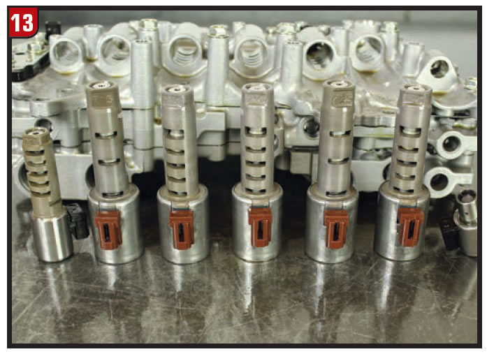
- The PCS is a normally open type linear solenoid which controlling main line pressure.
- SS3 is a normally open type linear solenoid controlling 3-5-R brake clutch pressure.
- SS2 is a normally closed type linear solenoid controlling 2-6 brake clutch pressure.
- CCS is a normally closed type linear solenoid controlling converter clutch apply pressure.
- SS4 is a normally open type linear solenoid controlling high & reverse clutch pressure.
- SS1 is a normally closed type linear solenoid controlling low clutch pressure.
The On/Off solenoid is a normally open type solenoid, which strokes select valves 1 and 2 allowing the SS4 solenoid to control pressure to two different clutch assemblies.
- All linear solenoids measure between 5-7Ω at 76°F
- On/Off solenoid measures between 11-14Ω at 76°F
Figure 14 shows the two pressure switch manifolds that are on this valve body. The pressure switch assembly located on the left is called “Pressure Switch A Manifold”. The left pressure switch in this manifold monitors the 2-6 brake clutch while the switch on the right monitors the 3-5-R brake clutch.
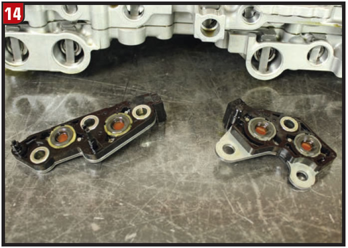
The pressure switch assembly located on the left is “pressure switch B manifold.” The left pressure switch in this manifold monitors the high clutch while the switch on the right monitors the low clutch.
Mazda Bulletin 05-005/14 speaks of a check-engine light and an automatic transaxle warning light becoming illuminated with codes P0842, P0847, P0872 and/or P0877 being stored in memory. DTC P0780 and/or P1738 may also be stored together.
- P0842: Oil pressure switch No. 1 (oil pressure switch B) stuck on
- P0847: Oil pressure switch No. 2 (oil pressure switch A) stuck on
- P0872: Oil pressure switch No. 3 (oil pressure switch A) stuck on
- P0877: Oil pressure switch No. 4 (oil pressure switch B) stuck on
- P0780: Gear shifting malfunction
- P1738: Automatic transaxle internal malfunction
The bulletin explains that this is caused by the oil pressure switch manifolds A and/or B at the control valve body temporarily or permanently getting stuck due to contamination entering the passage (lots of metal on that magnet!). To correct the problem, some mass production changes have been implemented to reduce contamination and improve the DTC diagnostic logic.
New pressure switch manifolds are to be installed followed by reprogramming the TCM to the latest version as well as the PCM to the latest calibration.
- Pressure Switch Manifold A part number is FZ01-21-2C0
- Pressure Switch Manifold B part number is FZ01-21-2J0
Next month’s article will get inside this transmission to see what caused all that metal.


