


A Ford Bronco was towed into the shop for a routine manual transmission clutch replacement. Apparently, the owner of the vehicle felt the need to squeeze out a few more miles before repairing, but unfortunately his math was off just a bit. By the time the vehicle got to the shop it wouldn’t move at all.
The Bronco was equipped with a 5.0L engine and a four speed “stick” transmission and although the vehicle had a fair amount of miles on it was not too bad of shape so the owner decided to go forward with the repair.
As far as clutch jobs go, yanking the transmission and clutch was not overly difficult, so the repair seemed to be rather routine. The flywheel surface was turned, the replacement clutch assembly was delivered and turned out to be the right one, which at times could be a difficult thing and no other external components needed replacement.
The clutch and transmission were reinstalled with-out incident, however when the engine was fired up and the transmission was shifted into reverse, things got ugly due to a noticeable grinding noise. The situation wasn’t much better going into the first gear but at least there was no grinding noise because of the synchronizer. The question became what was up with the clutch.

Since newer vehicles are outfitted with hydraulic release components instead of mechanical release items, there is really no free travel to deal with; therefore, only a couple of conditions can create clutch drag. A tight pilot bearing or bushing could cause the input shaft to rotate as well as the clutch disc not sliding easily on the shaft splines. Such was not the case with the Bronco.
Hydraulic systems do not like air, which can create certain issues depending on location and volume, so every effort is needed to make sure that there is none. Air in a brake system will usually result in a spongy petal that can be quite noticeable. A hydraulic clutch system containing air ends up with what the Bronco had, which was no release. It could be argued that the technician failed to perform a simple procedure, which merely involved turning a screw; however, that definitely was not the case. The fact is that the hydraulic release system on the Bronco had no bleeder screw to turn including the slave cylinder (Figure 1). There is a brass screw that is located next to the hydraulic line installed by the manufacturer that should not be removed because it will damage the housing.
It is questionable as to why a manufacturer would design the hydraulic clutch release system without a simple bleeder screw located in a convenient position but they have. It certainly is not the cost of the bleeder or assembly, although it could be. It may be a good idea for OE production but it definitely makes things more difficult doing a repair.
This approach was not limited to Ford because GM also chose to release certain models without a bleeder screw, such as specific years of the Chevy Camaro (Figure 2). Note the plastic straps on both brands of slave cylinder that holds the plunger inward. The purpose is to keep the piston in a certain position until the clutch pedal is applied at which point the straps will break. The piece of plastic at the end of the push rod actually provides lubrication for the fork.
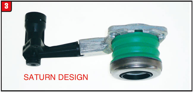
Another manufacturer to provide a release system without a bleeder screw, although short-lived, was Saturn. The slave cylinder used by Saturn was noticeably different than Ford or GM (Figure 3). The end result, however, was the same, a hard to bleed system.

Regardless of the manufacturer, the task is still the same, which is to expel air from the system. Fortunately, in any liquid air rises to the top and that is a plus for the technician. LuK, the clutch assembly manufacturer, among others has developed a procedure to address this issue and can apply to most models that have a non-bleeder screw system. Other procedures may also exist.
To begin with, push the slave cylinder pushrod inward and disconnect the plastic strap to enable the pushrod to fully extend. Do not cut or damage the retaining strap. Next, tilt the slave cylinder at a 45°angle with the master cylinder line port facing up. At this point fill the slave cylinder with brake fluid as much as possible and insert the master cylinder hydraulic line. Make sure to lubricate the O-ring and install any retaining pins.
Hold the slave cylinder vertically with the push rod facing downward. If the hydraulic line prevents the slave from being angled completely vertical, then angle the cylinder downward as much as possible without bending or damaging the line. In addition, the slave cylinder must be lower than the master cylinder.
With the slave cylinder in the downward position, push the pushrod into the cylinder approximately 1 inch, watching for air bubbles in the master cylinder reservoir. Repeat moving the pushrod in and out approximately 10 to 15 times until all air bubbles are gone.
With all the air purged from the system, slowly push the slave cylinder pushrod back into the cylinder and reconnect the plastic strap. Install the slave cylinder with the plastic strap in position.
As stated, the straps will break once the petal is pushed, leaving part of the strap positioned between the pushrod and fork. A similar process can be used on different vehicles.
At some point, maybe the manufacturer will consider subtle changes like this and how it affects the repair industry.


When the 6T40 was released in 2008 internal components remained relatively stable at least for a while, but as they say, all good things must come to an end. With the exception of specific differences between the 6T40 and 6T45 to satisfy torque capacity requirements, the units had about a four-year run that was somewhat uneventful. That all changed in 2012.
Transmission changes and upgrades have occurred almost from the beginning to address calibration and durability issues. As time went on weight reduction also became a prime concern of the OEMs. The explosion of electronics and electrical items used to control every aspect of the transmission had also resulted in a plethora of changing components. For some time now fuel economy has been a big driver in transmission design. The changes implemented on the 6T40 family of transmissions beginning in 2012 not only focused on electrical issues by adding CPL (clutch pulse learn) for shift strategy but also to address clutch drag during release of a given clutch pack.
Previous failure areas on the 6T40 involved the pressure switches that were part of the TEHCM assembly, however that’s no longer a concern because the pressure switches are gone. In addition, the notorious 3-5/Rev wave plate breakage created a lot of headaches and was subsequently redesigned along with the entire 4-5-6 clutch assembly. Failures now seem to be less but time will tell.
One of the biggest obstacles that technicians are now facing is what goes where and when. The day of changes and upgrades being limited to a drop dead month or even year are rapidly disappearing as in the case of the 6T40. The three main designations for identifying the design level of the 6T40 is GEN 1, GEN 2 or GEN 3 (GEN for generation), however a few items can also be classified by 1st design or 2nd design. Although GEN 2 models started to hit the street in 2012, GEN 1 transmissions hung around through 2013. The same is true concerning GEN 3 models that were released in 2014 with GEN 2 transmissions lasting well beyond 2014. At this point the most important item on the scorecard for identification is the RPO code. Beyond that is to contact the nearest trusty dealership.
Friction-plate design change for the two rotating clutches has not been too bad so far, although that could change. Both the 3-5/Rev and 4-5-6 plates were tweaked in 2012 and have held the line thus far. The 3-5/Rev friction material remained the same but was grooved and the wave height was increased slightly for 2012. The 4-5-6 friction material was changed from tan to gray with a slight change in grooving, although clutch quantity was changed from 4 to 5 in 2012.
The three stationary brakes are a different matter altogether. Not only were the changes more involved but trying to pigeonhole the start and end production dates are more difficult.
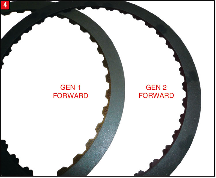
Forward (1-2-3-4) clutch: When first released the forward friction material was smooth and had a slight wave in the steel core (approximately 0.2 mm) under OE part number 24248898. In preparation for the 2012 GEN 2 applications another forward friction was released under part number 24268545, although this and other forward clutch part numbers are NLA. Physically the newer plate looks the same as the previous friction with the difference being a slightly taller wave, approximately 0.4 mm (Figure 4). The main identifier of the newer plates is the notches located on each tooth. This wave height change was done of course to reduce clutch drag during release.
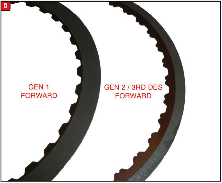
Apparently, that change was not good enough, so beginning in 2013 another forward friction was introduced under part number 24273076, along with noticeable changes (Figure 5). To reduce clutch drag even further the inside diameter of the friction wafer was increased and the total outside diameter was decreased. Torque capacity must not be an issue since clutch quantity remains the same and the new part number supersedes all previous GEN 2 numbers that are much wider. Lastly, in 2015 certain transmission models received yet another design friction plate that has tan friction material and 8 oil grooves under part number 24273086. Dimensionally the two latest part numbers are the same, at least for now.
Intermediate (2-6) clutch: When GM first released the 6T40 it was determined that the same friction plate used in the forward position could also be used for intermediate. That thinking went south in preparation for GEN 2 models resulting in different part numbers. Unlike changes to the forward frictions, changes to the intermediate frictions have been somewhat limited to grooving pattern. The GEN 1 friction material was smooth as stated. So far the material itself and the amount of wave in the steel core have remained same.
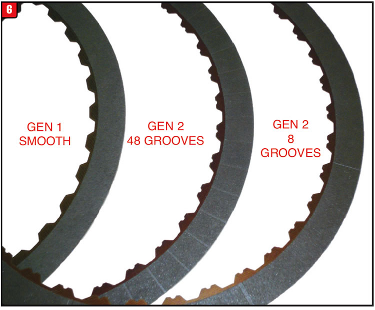
The first GEN 2 intermediate friction to be released for 2012 contained 48 grooves under part number 24260698 (Figure 6). As with other GEN 2 friction plates there are notches in the teeth for identification purposes. That particular change apparently was not sufficient because another friction plate was introduced in 2013 under part number 24263895; however, the amount of oil grooves were reduced from the previous 48 down to 8. Lastly and based upon model, a fourth friction part number (24273084) was released for late 2013 and beyond which also has 8 grooves. Normally that type of change would impact application as much as release, but who’s to say.
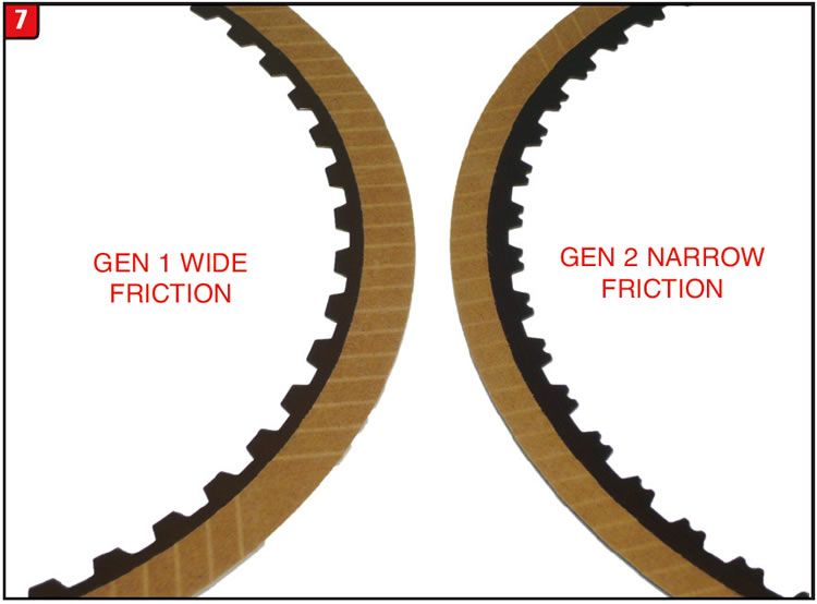
Low/reverse clutch: The other sta-tionary brake also got a facelift a couple of times in part for the same reasons. The first low/reverse friction plate to be developed for GEN 1 was a normal looking friction plate with tan material under part number 24231257. To accommodate the new concern about clutch drag for GEN 2 applications the plate was modified by making the ID of the friction wafer larger and the amount of waves was increased from 6 to 9 (Figure 7). The GEN 2 clutch plate also has notches in the teeth.
Lastly, beginning in 2014 a third design friction plate was released under part number 24273088 with the main difference being how it is manufactured. The newest design plate is segmented (button frictions), which is now the ongoing trend.
It is debatable whether engineers will continue to make these changes or leave well enough alone. Stay tuned.


A 2002 Highlander 3.0L using the U140 transmission comes back to Pedro Seda’s shop in Puerto Rico. He had rebuilt it two years prior to its return where it had worked flawlessly during this time. Then, in an instant, it went from flawless to faulty. The transmission suddenly lost reverse and would no longer shift into fourth gear. When reverse was selected an engagement was felt yet the vehicle did not move in reverse.
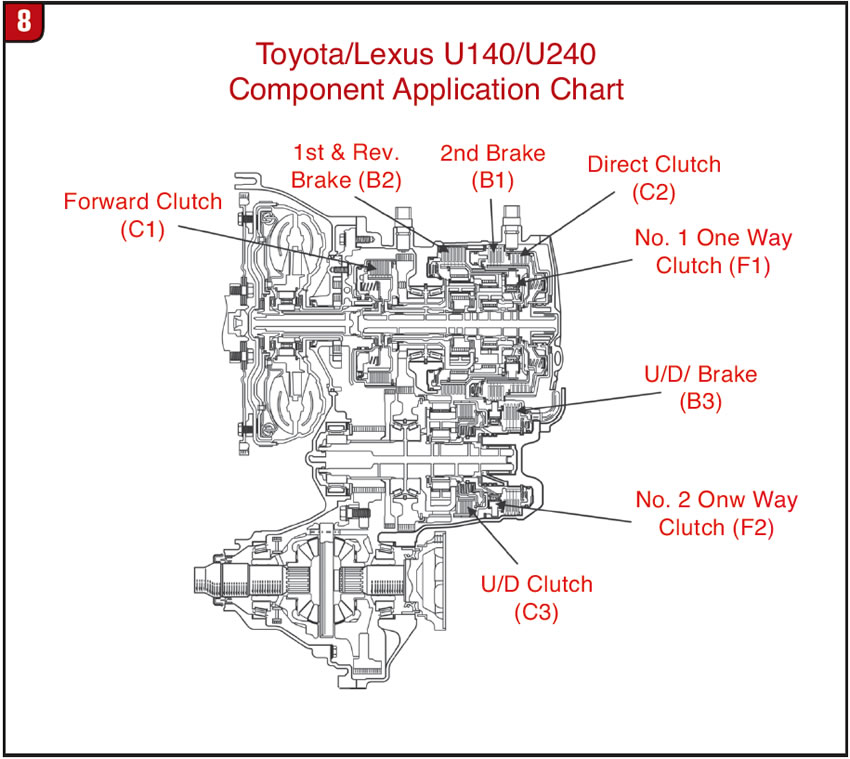
Reference was then made to a component application chart to begin diagnosing the problem (Figure 8). The chart revealed the Direct/C2 clutch, the L-R/B3 brake and the UD/B3 brake are applied in reverse. For fourth gear the Forward/C1 clutch, the Direct/C2 clutch and the UD/C3 clutch are applied. So by a process of elimination it appears that the Direct/C2 clutch may be the problem.
A pan inspection was then made. At first it was a big surprise to find that it was very clean, especially for it having been on the road for two years. But then, thinking about how the problem occurred so suddenly, rather than a typical C2 clutch burn out, something related to the clutch must have snapped, sheared off or broke.
Once the rear cover was pulled and the C2 clutch assembly removed, there was nothing obviously wrong. The drum, shaft, clutch hub, clutches, piston, pipes, seals, rings and cover were all in “pristine” condition.
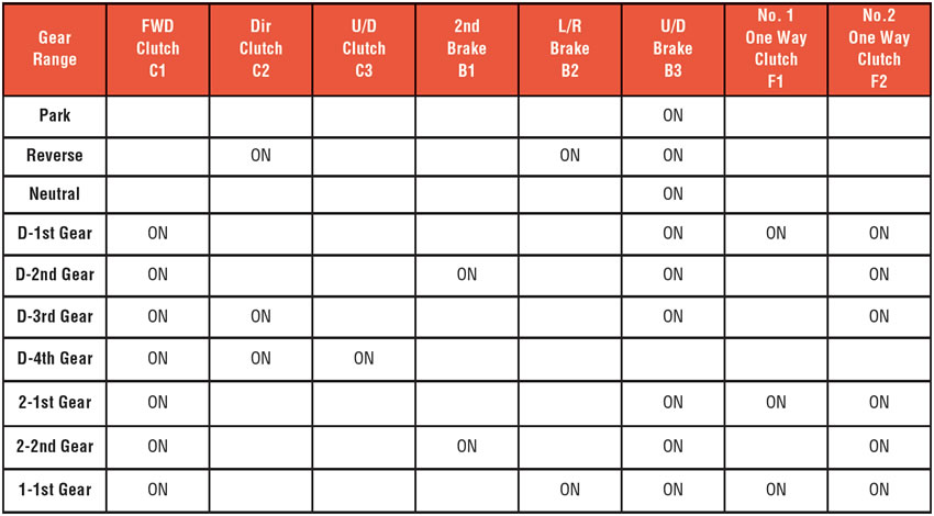
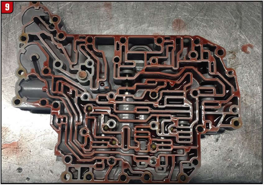
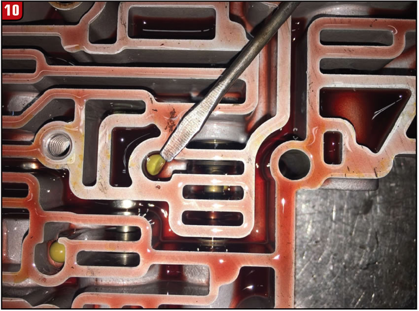
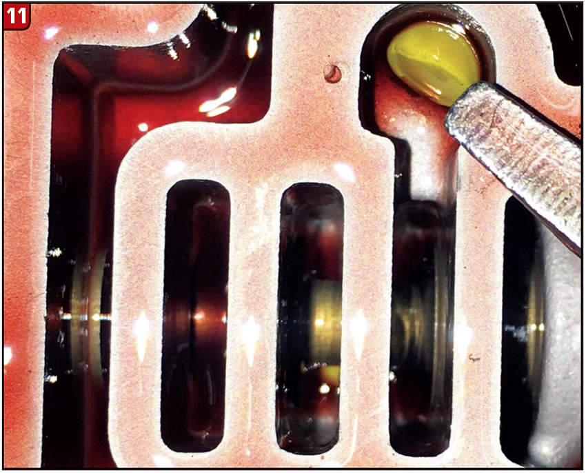
At this point the valve body was removed and disassembled. When looking into the lower valve body where the check balls are located (Figure 9), a check ball was found split in two (figures 10 and 11). So one would think “voilà,” we found the problem. The only problem is, the hydraulics provided in ATSG’s Tech Guide shows this ball as only controlling the flow rate in and out of the UD/B3 brake clutch.
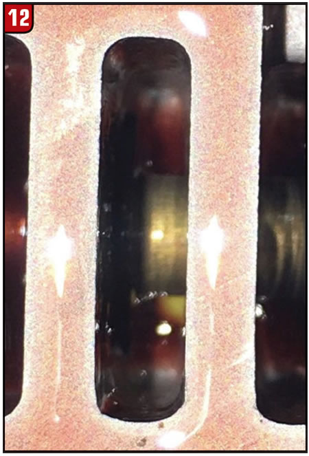
The question to ask now is where did the other half of the ball travel to? The valve where this ball sits along side of is the 3-4 shift valve. A closer look at this valve showed that the other half of this ball is wedged underneath that valve. This caused it to be stuck in a partially stroked position (Figure 12).
When this valve is held closed by spring tension it allows line pressure to be routed to this check ball. From this check ball line pressure is directed to the B3 clutch, B3 accumulator and the B3 orifice control valve. The valve was stuck in such a way that it blocked pressure to the B3 clutch, causing the no-reverse condition. The C2 clutch and the B2 brake applied which is why an engagement was felt, yet without the B3 brake there is no reverse movement.
The question that should be asked now is, if the B3 clutches are not applying, how is it that it moves forward yet has no fourth gear?
Two reasons will satisfy this question:
- The B3 clutches are not necessary for it to move forward as the number 2 one-way-clutch will hold the UD planetary sun gear from turning clockwise. The B3 also holds the UD planetary sun gear from turning clockwise but also prevents it from turning counterclockwise. This will provide engine braking during lift foot deceleration.
- When the selector lever is placed into drive, additional line pressure is sent to the 3-4 shift valve and is blocked at the valve when it is held closed by spring tension. This valve remains closed for first, second and third gears. When it is stroked to make the 3-4 shift, this additional line pressure is then routed to the UD/C3 clutch for fourth gear. The 3-4 shift valve was jammed by the half ball in such a way that it blocked this pressure from applying the C3 clutch.
In conclusion, Pedro Seda was a victim of “double jeopardy.” A split ball jammed one valve causing two different problems.

May 2017 Issue
Volume 34, No. 5
- Ford Bronco clutch replacement procedure
- GM 6T40 Friction Plate Design Changes
- No Reverse or 4th Leads to Double Jeopardy


