


Even in 2015, many repair facilities shy away from taking in a vehicle with a CVT (aka snowmobile transmission). This reluctance stems from a lack of familiarity, diagnostic information and parts, although information and product is becoming more readily available over time.
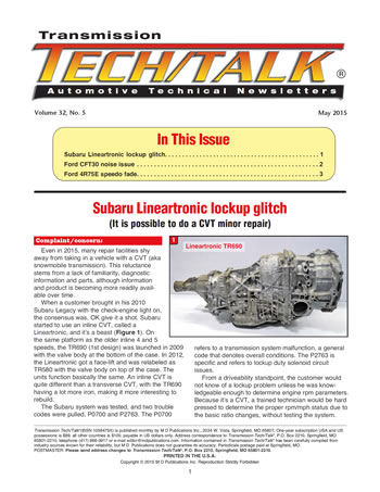
When a customer brought in his 2010 Subaru Legacy with the check-engine light on, the consensus was, OK give it a shot. Subaru started to use an inline CVT, called a Lineartronic, and itʼs a beast (Figure 1). On the same platform as the older inline 4 and 5 speeds, the TR690 (1st design) was launched in 2009 with the valve body at the bottom of the case. In 2012, the Lineartronic got a face-lift and was relabeled as TR580 with the valve body on top of the case. The units function basically the same. An inline CVT is quite different than a transverse CVT, with the TR690 having a lot more iron, making it more interesting to rebuild.
The Subaru system was tested, and two trouble codes were pulled, P0700 and P2763. The P0700 refers to a transmission system malfunction, a general code that denotes overall conditions. The P2763 is specific and refers to lockup duty solenoid circuit issues.
From a driveability standpoint, the customer would not know of a lockup problem unless he was knowledgeable enough to determine engine rpm parameters. Because itʼs a CVT, a trained technician would be hard pressed to determine the proper rpm/mph status due to the basic ratio changes, without testing the system.

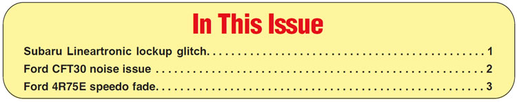
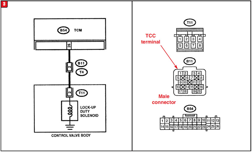
Focusing on code P2763, the lockup system needed to be checked out to determine how far to go into the unit. On top of the transmission case are two electrical connectors, one black and one gray. It is the gray connector that contains the internal solenoid wiring. Subaru refers to that connector as T4/B11, and it does have a lot of pins. All solenoids are internally grounded; therefore, testing resistance means merely hooking the meter to a particular connector pin and the case (Figure 2).
There are two lockup solenoids. One is for lockup timing, and the other is for lockup apply firmness. The P2763 is for lockup duty which is terminal #2 in the connector (Figure 3). Resistance for the lock-up duty solenoid should be between 10-13 ohms. Once the meter was connected, it became clear as to the source of the problem. The solenoid measured 68 ohms resistance, just a tad over the norm.

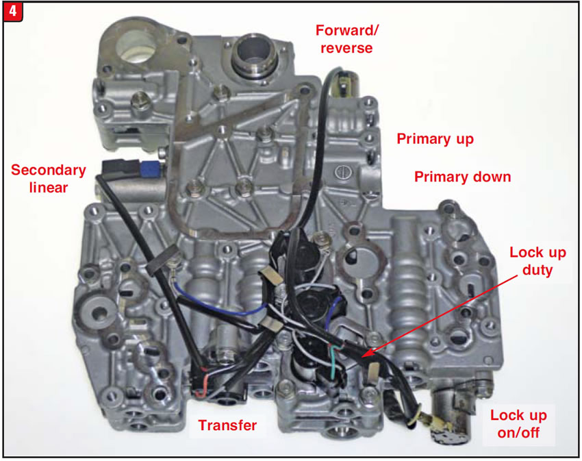
With that, the pan and filter were dropped to gain access to the valve body. Unlike most other valve body/solenoid arrangements, the TR690 has a single internal harness connector to unplug. The valve body contains seven solenoids, two linears, four pwmʼs and one on/off type solenoid (Figure 4). The solenoid types are listed accordingly.
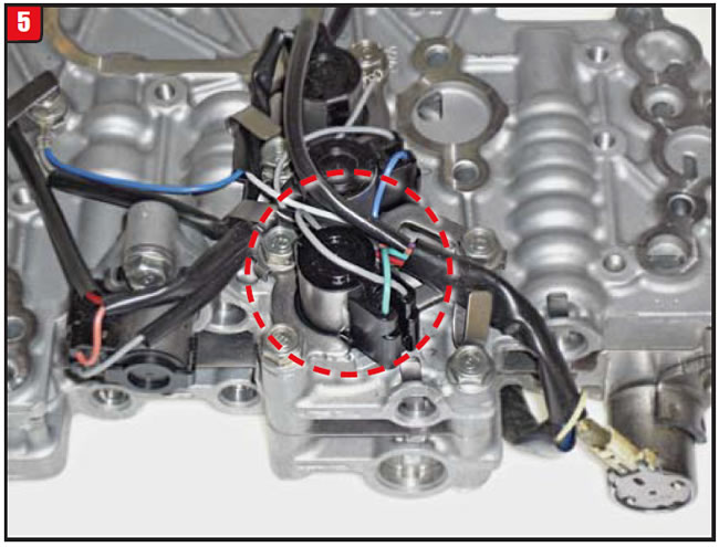
The lockup duty solenoid is one of three of the same type of solenoid. The lock-up duty, primary up and primary down are in a row and has one hold-down bracket. The lockup duty is at the end (Figure 5). It is not a simple task to pop off the harness connector like other types. First, remove the hold down bracket in order to lift the solenoid out of the bore, due to a valve-bore retainer being in the way.
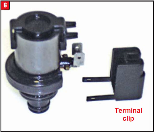
Use caution when removing the connector cap by moving it outward and push the two wires out of the grooves. The wires have spade terminals that plug into the solenoid terminals. The cap has lineup prongs that can easily break (Figure 6).
The solenoid was replaced with a good one, reassembled, and taken for a road test. Lockup worked well, and there were no more trouble codes. Problem solved. Rebuilding the transmission, however, could be a different matter.


A customer was experiencing a noise on his 2005 Ford Freestyle that prompted him to bring in the vehicle. It was taken for a road test to determine what was wrong, and overall the unit worked fairly well. The transmission is a CFT30, which is a CVT produced by ZF, before the company exited that segment of transmission production.
CFT30 noise can stem from a variety of different bearings which do tend to fail. The vehicle had 58,000 miles on it, and when the pan was dropped, the inside was pretty clean. Not a lot of debris. It was determined to remove the transmission and address the bearing noise, since everything else seemed OK.
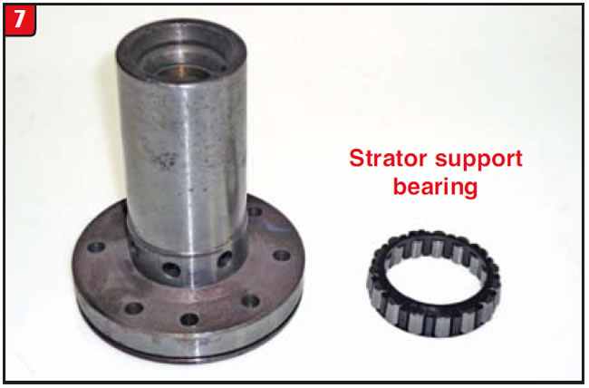
The unit was popped out, the valve body removed and the Bell housing was split from the case to look for bearing damage. There were actually two bearings that needed to be replaced, both caged bearings. The first bearing was the stator to input shaft bearing, part# (5F9Z-7052A) (Figure 7). Fortunately, the bore of the stator support and journal of the input shaft were not damaged.
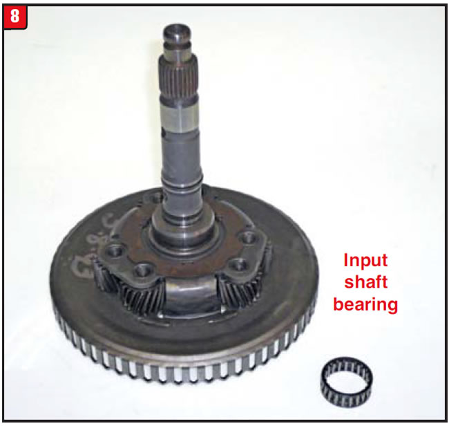
The second bearing was on the back side of the input/planet assembly, part# (5F9Z-7N168C) (Figure 8). As luck would have it, the bore of the planet and the bearing journal of the drive pulley (variator) where the bearing road was also in good shape. The transmission winds were blowing well so far. As a precaution, the forward clutch was also inspected since it was right there and the frictions showed no sign of slippage or wear. An overhaul kit was available, so gaskets and seals were replaced.
The unit was reassembled and installed into the vehicle, the correct CVT fluid added, and it was taken for a road test. At that point, things got a little nasty. Not only was the initial application not as before; the transmission did not respond well overall. In addition, the good old check-engine light came on. A scanner was connected, and three trouble codes were pulled, P0845, P0868 and P0964. The codes referenced solenoid, variator and pressure issues. Since the unit worked well when the customer brought the vehicle in, these problems were obviously man-made. Diagnosis became even more of an issue since the CFT30 is a Mechatronic transmission, meaning that the valve body has a TEHCM. At least the noise was gone.
The question remained: What was misassembled or damaged to have caused all of that carnage? Normally a transmission has several clutch packs that can cause issues. In the case of the CFT30, there is only the forward clutch that can create problems going forward. The other items, beyond the forward clutch, that can cause apply issues are the drive and driven pulleys, which were not tampered with at all.
One concern was the TEHCM unit and whether it had been damaged somehow by static electricity. Caution should always be used to avoid contact with the TEHCM pins. The TEHCM seemed OK.
At this point, the pan was dropped to look for anything out of whack. Since nothing was visible in the pan, the filter and valve body were removed to do some air checks. The forward clutch pack was thoroughly air checked to make sure that the seals were not cut during reassembly, and it air tested well. Conditions were almost to the point of removing the transmission when something was noticed concerning the valve body. The connecting tubes seemed to be a bit off.
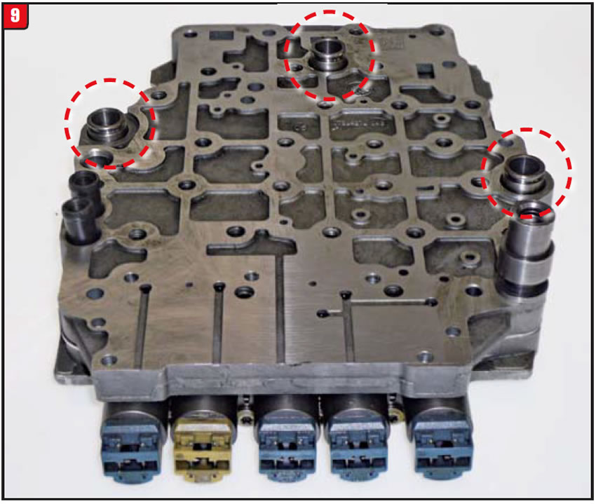
Unlike most transmission types, the CFT30 valve body not only has a flat machined surface that mates with the case surface but also has several tubes for oil transfer as well (Figure 9).
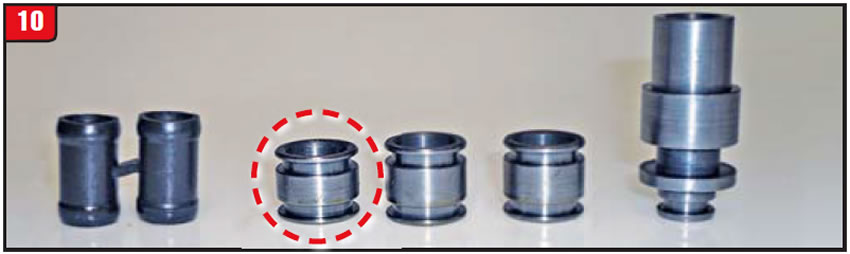
The twin tube is rubberized and is used for TCC. The tubes should always be replaced. The largest tube has O-rings inside and out and is for the manual valve. The three remaining tubes are the issue because they are the same diameter and use the same O-rings, but they have one exception, which is the length (Figure 10). Transmissions produced before December 2005 have two long tubes and one short one.
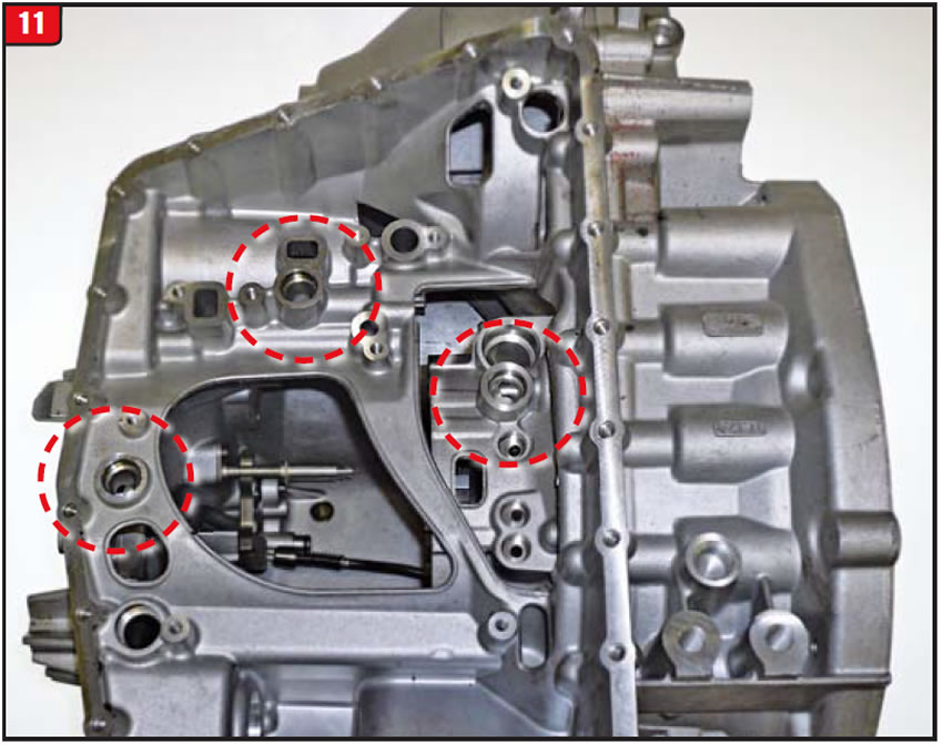
ZF must have realized this potential problem because after December 2005 all three tubes became the same length, which was short. The reason early-model tubes differed in length was that the two long tubes were between the valve body and case, and the short tube was between the valve body and Bell housing. The Bell housing surface is higher than the case surface, and using the longer tube will not allow the valve body to fit tightly against the case, resulting in cross leaks, (Figure 11). The tubes were repositioned and everything worked well.
When repairing a CFT30 or any transmission with connecting tubes, always scope out the dimensions because “little things can make matters worse.”


A customer with a 2008 Ford F150 “pick em” up truck started to notice the speedometer going buggy while driving down the road. The vehicle had a 4R75E transmission with 4WD and had 97,000 miles on it. The condition was erratic because at times it worked well. In addition to the speedo fading (dropping), a check engine light would come on.
Initially, the vehicle was taken to another repair facility to rectify the problem. The shop road tested the vehicle and witnessed the erratic speedo as well as hooking up a scanner to pull trouble codes. Itʼs unknown what particular codes were pulled; however, the technician decided to replace the transfer-case speed sensor (TCSS). After the repair was done and the codes were cleared, the vehicle was driven and apparently worked well, according to the customer. It worked well for a couple of days, that is, when the speedo started to act up again.
After a couple of trips back to shop #1, the customer decided on plan B and showed up here loaded for bear. The issue was verified during the road test and just as the first shop experienced, the speedo reading was erratic. Another scanner was connected and one trouble code was pulled, P0500. The P0500 code refers to a vehicle-speed sensor issue, but with more than one possible cause (Figure 12). As shown in the chart, components that can contribute to P0500 range from the transfer-case speed sensor (TCSS), which already was replaced, to the transmission VSS (OSS), to the ABS module and wheel sensors, etc, etc. The problem was everything tested OK, at least individually.
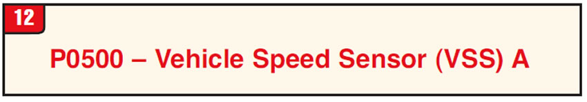
P0500 – Vehicle Speed Sensor (VSS) A
Description
Indicates the powertrain control module (PCM) detected an error in the vehicle-speed information. Vehicle-speed data is received from either the VSS, the transfer-case speed sensor (TCSS) or the anti-lock brake-system (ABS) control module. If the engine rpm is above the torque-converter stall speed (automatic transmission) and the engine load is high, it can be inferred that the vehicle must be moving. If there is insufficient vehicle-speed data input, a concern is indicated and a DTC is set. On most vehicle applications, the malfunction indicator lamp (MIL) is illuminated when the DTC is set.
Possible causes
• Open in the VSS+/VSS– harness circuit
• Open in the TCSS signal or the TCSS signal-return harness circuit
• Short to GND in the VSS harness circuit
• Short to GND in the TCSS harness circuit
• Short to PWR in the VSS harness circuit
• Short to PWR in the TCSS harness circuit
• Damaged drive mechanism for VSS or TCSS
• Damaged VSS or TCSS
• Damaged wheel-speed sensors
• Damaged wheel-speed sensor harness circuits
• Damage in the module(s) connected to the VSC/VSS circuit
• Open or short in the vehicle speed circuit VSS signal between the ABS VSS signal output and the VSS signal inputs to the PCM and other modules (F-Super Duty)
Diagnostic aids
Monitor the VSS PID while driving the vehicle. This DTC is set when the PCM detects a sudden loss of vehicle speed over a period of time. If vehicle-speed data is lost, check the source of the vehicle-speed input: VSS, TCSS or ABS.
Note: On some manual shift-on-the-fly (MSOF) applications, VSS and TCSS PID can be monitored. However, if no TCSS PID is available and VSS PID is zero, TCSS circuitry frequency must be checked for loss of sensor signal. If another vehicle electronic module has generated the P0500 and the vehicle does not receive its vehicle-speed input from the VSS, TCSS or ABS, check the PCM for output shaft-speed (OSS) sensor DTCs. On OSS applications, the PCM uses the OSS to calculate the vehicle speed. If no OSS DTCs are found, check for correct PCM configuration, tire size and axle ratio.
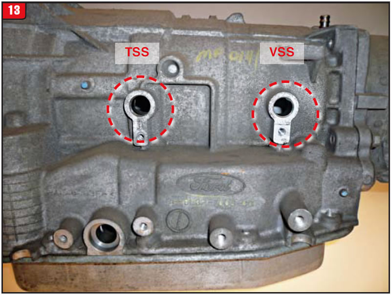
Based on the fact that the condition was erratic, it was decided to replace the transmission VSS in the event that it was providing inconsistent signals. There are four models of the 2004 up 4R70W family, (4R70W, 4R75W, 4R70E and 4R75E). The basic difference between them is the W and E types. They all have the rearward positioned VSS (OSS), whereas only the E models have the TSS located toward the center of the case (Figure 13).
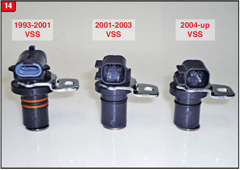
In addition, there are two different types of square connector VSS. The 2001-03 is long and the 04 up is short. They do not interchange, so use the correct one (Figure 14).
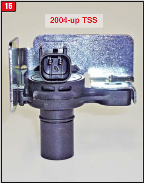
The center mounted TSS is a bit different from the OSS (VSS), in that the bolt tab spacing is longer and the TSS has a shield around it, (Figure 15).
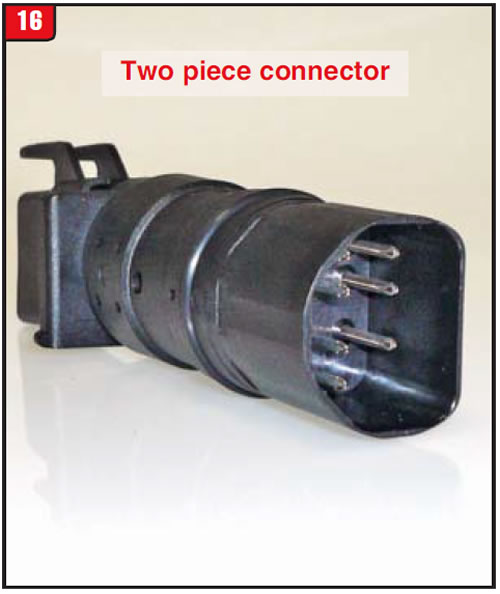
Apparently, all the jerking around of the harness during the sensor replacements was causing temporary contact of certain terminals. Since all roads lead to Rome, or in this case, the main electrical-case connector, the harness plug was pulled to look for corrosion. There was no corrosion; however, something else was amiss. It was loaded with ATF. The hardwire case connector is a molded type, yet fluid was able to wick up through the pins and create a short, at times. The connector is actually a two-piece hardwire design (Figure 16). All 4R70 models went back to a soft wire design in 2009.
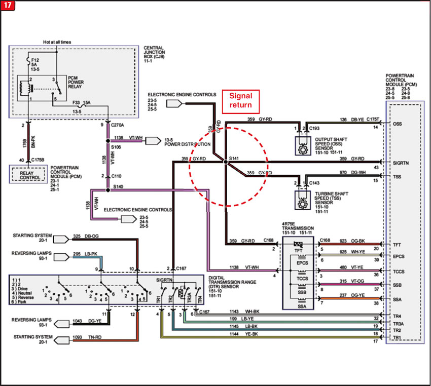
In addition to the VSS issues was an occasional flag concerning the TFT. This is because pin #2 is a signal return for the OSS, TSS, DTR and TFT (Figure 17). With that arrangement, anything can happen, and did.
Always refer to available info such as schematics and not just pick the logical item.

May 2015 Issue
Volume 32, No. 5
- Subaru Lineartronic lockup glitch
- Ford CFT30 noise issue
- Ford 4R75E speedo fade


