


Underdrive/overdrive-clutch stack-up issues relating to parts interchanging as well as interchangeability of electrical components.

Although the 45RFE (545RFE) and 68RFE transmissions are different, Chrysler has taken steps to standardize certain components. Standardizing certain components can, in effect, make it more difficult to distinguish one item from another due to subtle changes. Itʼs a no-brainer when “like” items are substantially different in appearance. Component changes/upgrades occur because of more than just standardizing. Changes are also made to enhance manufacturing efficiency or improve durability.
For instance, in 2007 with the launch of the 68RFE, the 45RFE pump body, pump cover (hub cap) and converter-seal layout were changed to reflect the 68RFE. The seal was relocated from the pump body to the tin pump cover, thus eliminating the body-to-cover lathe-cut seal. That change certainly improved the manufacturing process.

Torque-capacity demands of the 45RFE and 68RFE required a different underdrive-and overdrive-clutch arrangement. The 45RFE (545RFE) U.D. and O.D. frictions are double sided, whereas the 68RFE U.D. and O.D. internal and external plates are single sided. The quantities of each design are different as well. Note: 45RFE (four speeds) and 545RFE (five speeds) are the same component-wise. Computer strategy is what makes the four-speed into a five-speed.
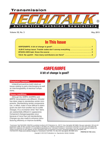
The housing that contains the U.D. and O.D. and reverse clutch packs is called the input retainer (Figure 1). Not only does the 45RFE input retainer resemble the A604 input retainer on steroids, but it also underwent a modification in 2007 relating to the underdrive pressure plate, just like the A604. The unending A604 U.D. pressure-plate upgrades had to do with snap-ring breakage problems (durability). The 45RFE/68RFE U.D. pressure-plate upgrade had to do more with capacity (standardization).
By repositioning the U.D. pressure-plate snap-ring grooves in the retainer, Chrysler was able to use one part for both transmission models, even though the overall clutch-pack stack-ups are different. When replacing the input retainer with one from another transmission, be sure of the year. The 1999-06 or 2007-up types are very similar.
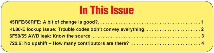
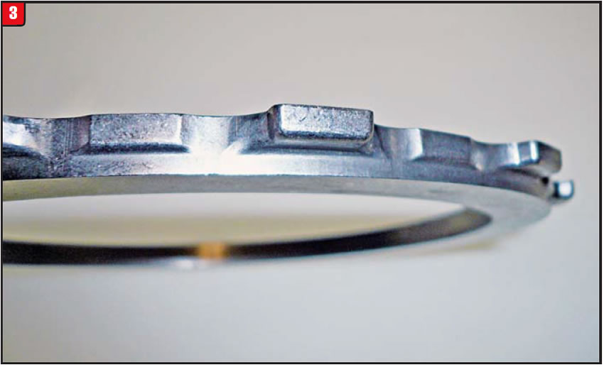
The other part of the equation is the U.D. pressure plate (Figure 2). Not only were the lugs (teeth) repositioned in 2007 to accommodate this upgrade, but also there are now two different thicknesses.
The lugs are offset toward one side on the ʼ99-06 style (Figure 3), whereas they are more toward the center on the 2007-up. The thickness of the ʼ99-06 and ʼ07-up 45RFE U.D. pressure plate is 0.295 inch. The thickness of the 68RFE pressure plate is 0.340 inch. As with the input retainer, use the correct pressure plate when replacement is required. Chrysler released a service package, part # 68009902AB, to service both the 45RFE and 68RFE transmissions.
The service package is, in effect, the 2007-up 45RFE design. Not only will it service the ʼ07-up 45RFE models, but as a package it also will back-service ʼ99-06 models. Both the input retainer and U.D. pressure plate must be used as a set for ʼ99-06 applications.
Although the package is listed for 68RFE repair, thatʼs not quite correct. The input retainer will work on 68RFE; however, the pressure plate will not. Therefore, either reuse the original pressure plate or, if needed, replace it with part # 52119658AB. Note: Selective U.D. pressure plates are NLA (no longer available).
Assemble all models with the correct frictions and steels and make sure clearances are acceptable. To beef up capacity, single-sided frictions can be installed into the 45RFE, with minor modifications.

Early 45RFE models used a solenoid block that had a black electrical connector. The design tended to be noisy and was changed to a new design in 2003/2004 (model dependent) with a white connector. The TRS plate was also changed and as a package would retro-fit to 1999. The black-connector design was discontinued. Another change that recently occurred may cause confusion. In 2011, a new solenoid block was released for production and does not contain an O.D. solenoid. The new block has a gray electrical connector. The new design is not yet available; however, the white-connector design will work on 2011-up models. The fact that the white-connector solenoid block has the O.D. solenoid is not an issue.
Standardizing, manufacturing, durability – it all applies!
A bit of change is good? You be the judge.


A 2004 Silverado with a 4L80-E experiences over-heating and, ultimately, transmission failure. In addition to other trouble codes, there was a P0300, which refers to an engine misfire problem.
After the transmission was repaired and road tested, it was determined that the unit worked well, except there was no lockup. Lockup did function with the use of a scan tool; however, it would not operate normally with the computer. A check engine light would appear, triggered by a P0300 code. The engine ran well with no sign of misfire.
Any time a code P0300 is set, the computer will disable lockup. The P0300 code can occur by other means than engine misfire. Sources of vibration that could also set P0300 might be driveshaft balance, rotor wobble and worn engine belts or pulleys. Normal lockup malfunction codes will not be set because the computer is just not commanding lockup.
Normally, when a problem arises on a vehicle that triggers a check engine light, the problem would be fixed, the code would be cleared and that would be that. The P0300 code, which will disable lockup, operates a bit differently.
When the cause of the P0300 trouble code is found and repaired, the code can then be erased. Even though the root cause of the problem is handled, the check engine light and code can reappear.
If this situation occurs, a specific operation needs to be performed. The operation is called a crankshaft-variation relearn procedure, and it requires a capable scan tool like a Snap-on Scanner or Tech II. The procedure is listed under function test on the scan tool and will cycle through a variety of steps and resets.
Once this procedure is completed and the behind-the-scenes issues have been reset, the check engine light should be off for good and, more important, lock-up should return.
This is but one example of how “trouble codes donʼt convey everything.”


A 2009 Ford Flex equipped with a 6F50 AWD transmission exhibits a right-side axle-seal leak. Fluid is dripping from the area of the AWD transfer case around the axle.
Road contaminants can get past the seal protector (stone guard) and cause either the axle seal or transfer-case seal to leak. Fluid from both seals ends up in the same place and may be misidentified. Wear on the seal journal of the axle shaft may also be present. Note whether the scratches/wear are on the journal at the seal or protector area. If the seal area is not affected, then merely polish the shaft.
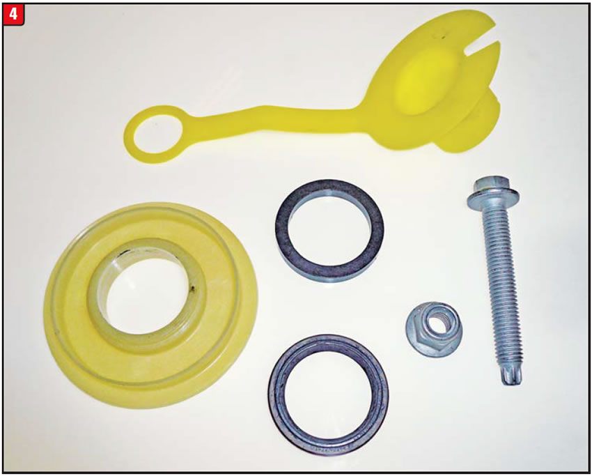
Because of the potential for seal leaks, Ford released a service kit, part # 8T4Z-7275-CD, which contains not only the axle and transfer-case seals but also an updated plastic seal protector (Figure 4).
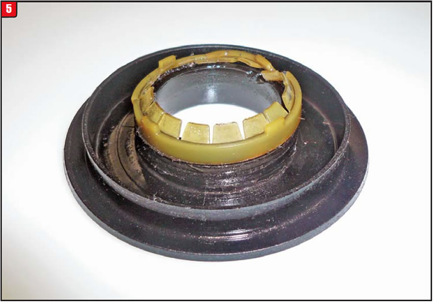
The new natural-color seal protector (deflector) has an inside diameter larger than the original black seal protector (Figure 5).
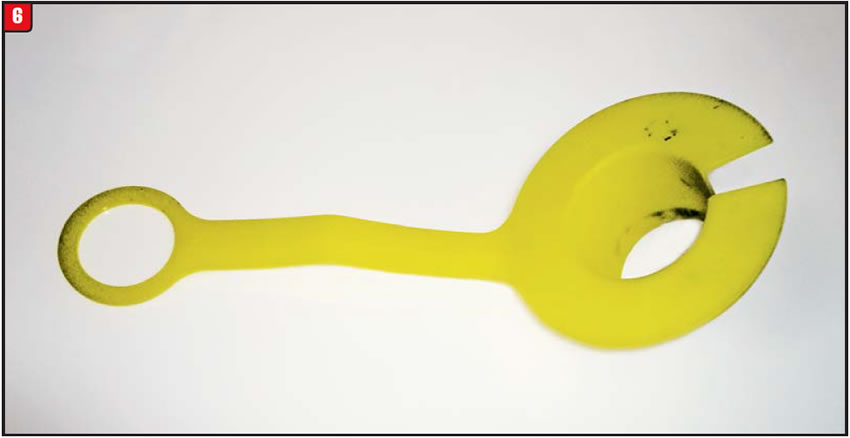
This was required to make room for the installation plug. The installation plug is split to go around the axle shaft and has a tab to make it easy to remove once the axle is in position. The plug is shown in Figure 6.
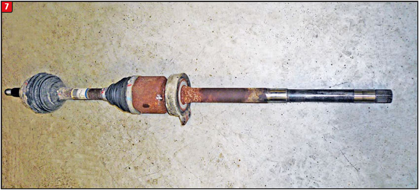
First, remove the axle shaft to expose the transfer-case/axle seals. The inner shaft has the final-drive side-gear splines and axle-seal journal, which as shown in Figure 7 are spaced apart by almost a foot. Once the shaft is removed, inspect the spline and journal areas for damage. As stated previously, slight damage to the journal at the seal-protector area is not a problem. Replace the shaft if the seal area is worn. Once the axle shaft is removed, the black plastic seal protector is accessible. The seal protector has a slight press fit but can be removed easily. Discard the protector after removal.
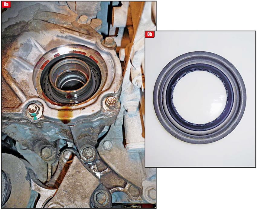
With the seal protector removed, the transfer-case and axle seals are visible (figures 8a & 8b). The transfer-case seal is the larger of the two and the seal lip rides on the transfer-case shaft. The axle seal and spacer are in the bore of the transfer-case shaft. Note the position of the seal before removal.
This arrangement is what can cause confusion as to whatʼs leaking. Is it transfer-case fluid or transmission fluid? Checking both fluids beforehand would help; however, if the leak is small, it may not be noticeable with fluid-level checks. Beyond that, the fluid color may be the indicator.
Use caution when installing all components, and follow the instructions that are included in the service package.
Install the axle seal to the depth of the original seal with the lip facing in. Next, place the Teflon (material) washer into the bore and push it up against the seal. The washer acts as a spacer and bushing to help center the axle shaft.
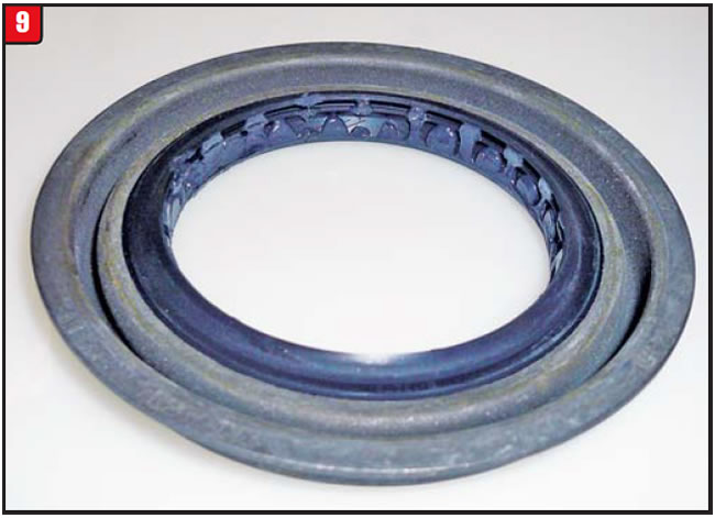
The larger transfer-case seal is flanged (Figure 9) and will bottom out once installed. Make sure that the protector is in to the proper depth. Last, insert the split seal plug into the seal protector until flush with the surface. Point the tab downward for easy removal. The plug actually goes all the way through the axle seal to protect it from the axle-shaft splines.
Start installing the axle shaft into the transfer case, and once the shaft is in far enough that the splines are past the axle seal, remove the split plug by pulling on the tab. With the split plug removed, push the axle shaft into the transfer case the rest of the way. Reassemble the control arm using the new ball-joint bolt and nut from the service package. The job is done and, more important, “the leak source is now known.”

A 2007 Jeep Grand Cherokee equipped with a Mercedes 722.6 transmission fails to upshift. In addition, a trouble code U0404 was indicated after a scan tool was connected. No other codes were set.
A malfunction with the console floor shifter was preventing the proper signal from being sent to the TCM. The code U0404 indicates an invalid data-signal issue from the shifter control module.
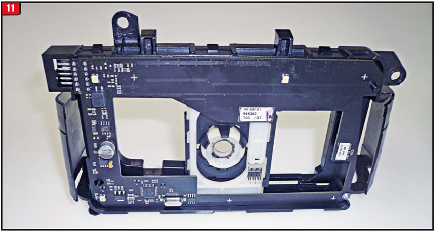
Various reasons can contribute to a no-shift condition, some internal, some external. Internal items that can cause shifting problems would include solenoids, sensors, pressure switches, valves etc. External items would include the ECM/TCM and related sensors, wiring harnesses or MLPS/DTR (or internal mode switch). Newer vehicle models have added another wrinkle: floor shifter controls with electronic modules (Figure 10).
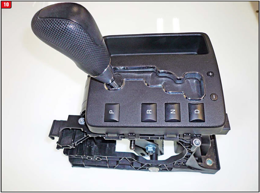
Shifters today are much more elaborate and provide more computer information than ever. To achieve that requires more electronics, along with more potential for problems. Beyond providing the basics of shifting from park to drive to manual low, shifters today also provide the ability to manually shift the transmission throughout the gear range and do it well. “Tap-shift” capabilities, no matter what the term, are a big selling point for the OEMs.
The internal components in todayʼs shifters would make big-screen TVs green with envy (Figure 11). Along with all that sophistication is an increase in cost. Some shifters do have certain components available separately, but others are all or nothing. In the case of the shifter in this Jeep Grand Cherokee, only the complete assembly was available, with a list price of $585. For that kind of money make sure that itʼs bad before replacing.
Before replacing any component for any reason, know the answer to the question, “How many contributors are there?”

May 2013 Issue
Volume 30, No. 5
- 45RFE/68RFE: A bit of change is good?
- 4L80-E lockup issue: Trouble codes donʼt convey everything
- 6F50/55 AWD leak: Know the source
- 722.6: No upshift – How many contributors are there?


