
Issue Summary:
- In a GM vehicle with a 4T65-E transaxle, code P1887 (malfunctioning TCC release switch) can be caused by any of several electrical or mechanical issues.
- On a 2004 or later Cadillac DeVille, switching the front tires with each other can illuminate a warning lamp in the driver information center.


A GM vehicle equipped with a 4T65-E transaxle comes to the shop with complaints of harsh shifting, no TCC operation and loss of fourth gear when hot. The Service Engine Soon light (MIL) may be illuminated at this time.
When the vehicle is scanned, a P1887 fault code, defined as a malfunction of the TCC release switch, is stored in memory. While this code is current, the PCM will inhibit TCC operation, freeze shift adapts and not allow fourth gear if the transmission is in Hot Mode.

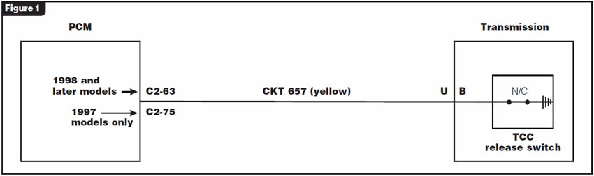
The PCM supplies 12 volts on circuit 657 to the TCC release switch with the ignition switch on or in the run position (see Figure 1).
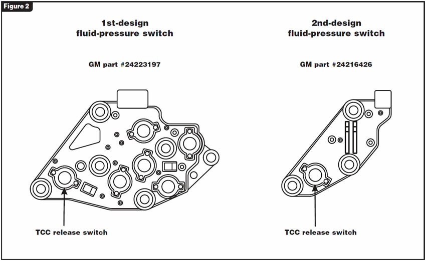
The TCC release switch is inside the transaxle as part of the fluid-pressure-switch assembly (see Figure 2).
This code is typically set when voltage on circuit 657 remains high for six seconds or longer when TCC is commanded on and TCC slip speed is -20 to +60 rpm. Possible causes for this problem include:
- An electrical issue could be an open in the signal circuit (CKT 657) between the PCM and the TCC release switch.
- A faulty TCC release switch.
- Damage to the turbine shaft, Teflon seal rings, O-ring or front-stator-support bushing.
- A worn or damaged drive sprocket and/or bearing or channel-plate sleeve.
- A sticking or worn TCC control valve or bore in the valve body.
- The #1 checkball in the channel plate leaking or not seating properly.
- A faulty PCM.

External electrical checks:
Scan-tool data may not display status of the TCC release switch.
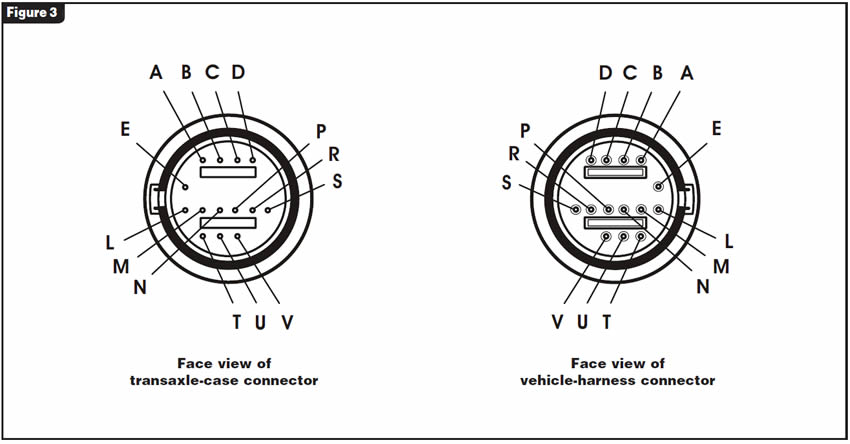
To test circuit 657, unplug the harness connector at the transmission and identify terminal U (see Figure 3). With a DVOM set to DC volts, place the negative lead to a known good ground and the positive meter lead to terminal U in the harness connector. Turn the key on with the engine off. You should see battery voltage.
If you see battery voltage at this time, proceed with Scenario 1.
If you do not see battery voltage at this time, proceed with Scenario 2.
Correction1:
(Scenario 1) If you do see battery voltage:
Turn the key off. Plug in the transmission harness connector and then turn key on again. Recheck voltage on wire at terminal U from wire-entry side of connector. You should not see any voltage. If battery voltage remains, either the internal harness is open or the TCC release switch is defective, as this switch is normally closed to ground without oil pressure present. Repair internal harness or replace fluid-pressure-switch assembly as necessary.
Correction2:
(Scenario 2) If you do not see battery voltage:
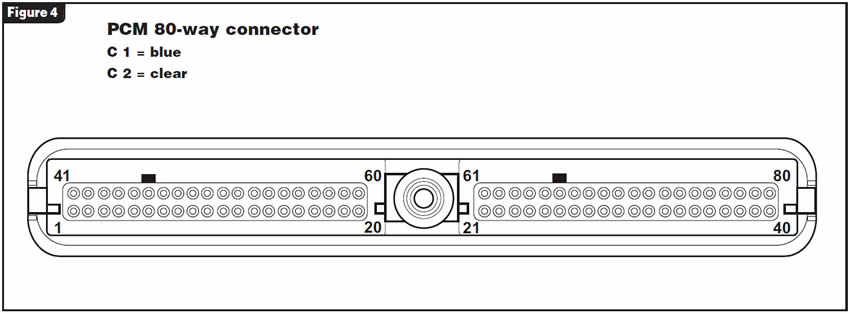
For 1998 and newer models, check voltage on wire at terminal 63 in the PCM C2 connector. For 1997 vehicles use terminal 75 (see Figure 4). If battery voltage is present, repair break in wire or run a new wire to terminal U in the transmission-harness connector. This is usually a yellow wire from the PCM to the transmission-harness connector.
If no voltage is present on wire at PCM connector, turn the key off, disconnect the battery and unplug the PCM connector. Remove terminal end and wire from connector to inspect for damaged crimp or broken wire. Test terminal end for loose fit on PCM pin. Repair as necessary. Plug connector into PCM. Reconnect battery. Turn key on and recheck voltage on wire at PCM connector.
If you now see battery voltage, verify that voltage is present at unplugged transmission-connector terminal U, and your repair is complete.
If there is still no battery voltage with key on/engine off and the transmission connector unplugged, then the PCM will require replacement.
Note: Electrically, this code can be set only by an open or break in circuit 657. An intermittent or constant short to ground on this circuit will not set code P1887.
Internal mechanical concerns:
- Check for damaged turbine shaft or loose inner steel sleeve. Replace turbine shaft as necessary.
- Inspect for worn or damaged turbine-shaft O-ring or seal rings and replace as necessary.
- Check for worn or loose drive-sprocket support bushing and replace bushing or support as needed (stator support).
A worn or damaged drive sprocket where it rides the bearing or a damaged bearing will require replacement of both pieces (see Figure 5).
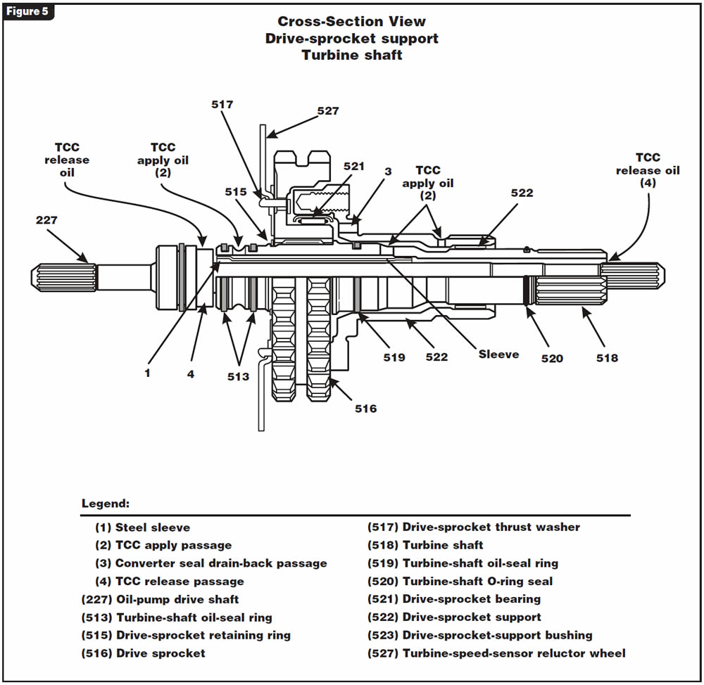
If the channel-plate sleeve has been damaged at the turbine-shaft seal-ring area from turbine-shaft mis-alignment due to failure of the drive-sprocket bushing or bearing, replacement of the sleeve or entire channel-plate assembly may be required.
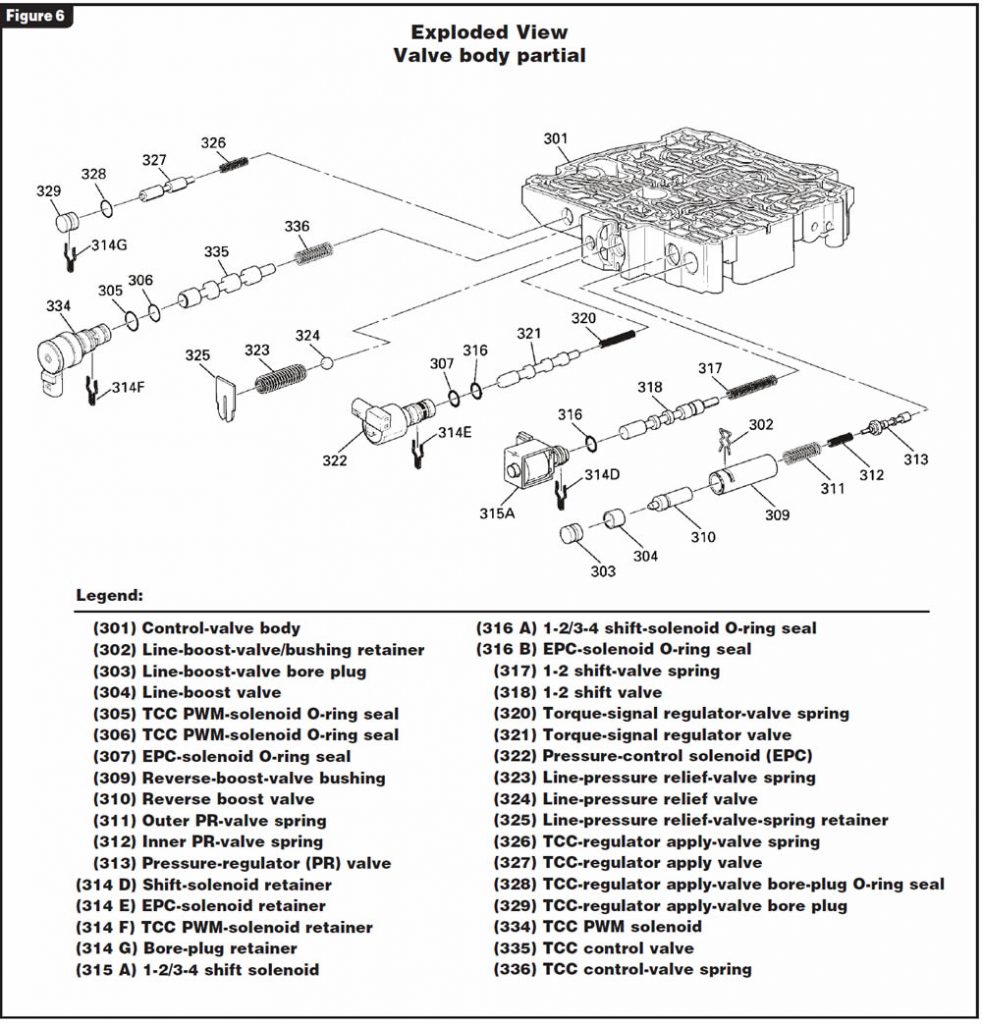
Valve-body concerns such as a sticking or worn TCC control valve or bore will require repair or replacement of the control-valve assembly (see Figure 6).
Look for metal particles or debris that would not allow the #1 checkball to seat properly. Clean or remove debris from the channel-plate area as needed (see Figure 7).

At the time of this printing, the current OEM part numbers are:
- 24223197 = 1st-design fluid-pressure-switch assembly
- 24216426 = 2nd-design fluid-pressure-switch assembly (Refer to Figure 2)


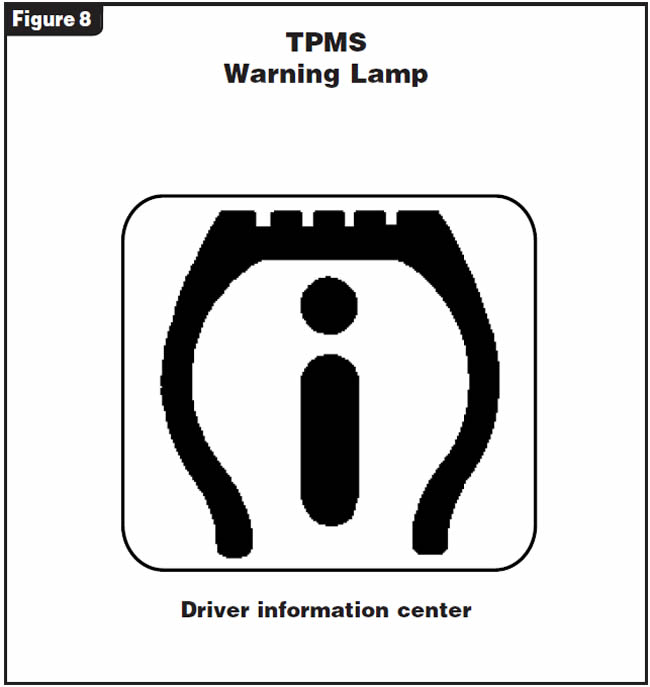
Transmission repairs have been completed on a 2004 Cadillac DeVille. After delivery to the customer, the car comes back to the shop with a complaint of an illuminated warning lamp that was not on prior to repairs. Figure 8 illustrates the warning lamp, which is for the tire-pressure-monitoring system (TPMS).
A scan of all areas of the PCM reveals no codes stored. However, when the body control module (BCM) is scanned, codes C0750 and C0755 appear, indicating there is a problem with both front tire-pressure sensors.
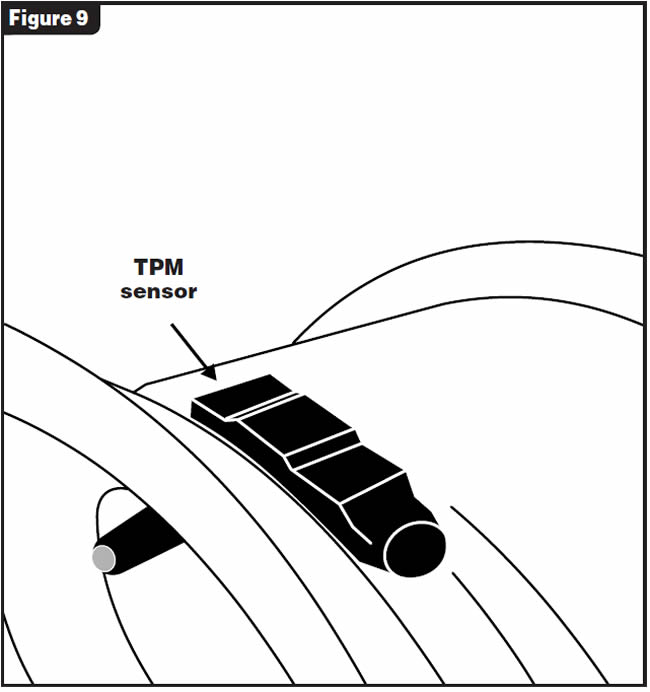
During the re-assembly of the vehicle, the left and right front wheels were switched with each other. This action caused the TPMS sensors in each of those wheels (see Figure 9) to alert the TPMS, turn on the warning lamp and store the codes mentioned. This occurs because this is a direct TPMS; in other words, it is a standalone system whose only purpose is to monitor tire pressures.
Indirect systems use the vehicle’s antilock-brake system by measuring wheel speed and should not be affected by switching wheel positions.
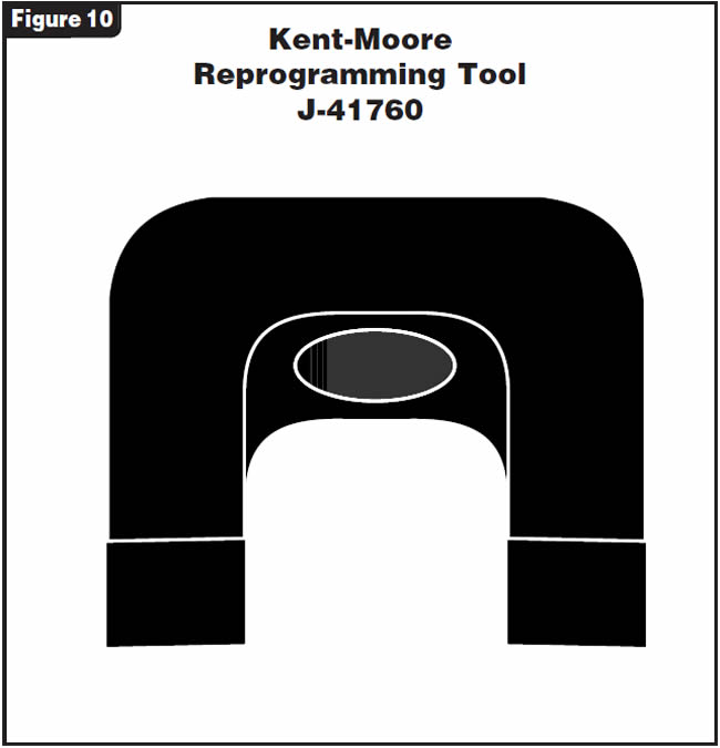
Anytime you rotate, balance or change the tires, or tire pressures are incorrect, you must reprogram the system. Reprogramming requires either a capable scan tool or the keyless-entry fob along with a magnet – which is Kent-Moore Tool J-41760, shown in Figure 10 – to accomplish a manual reprogramming.
The reprogramming procedure without the scan tool follows:
- Turn the ignition on.
- Using the key fob, lock and unlock the vehicle’s doors.
- Press the lock and unlock buttons at the same time; a single horn chirp will sound in about 10 seconds, indicating that the TPMS is in the relearn mode.
- Start with the left-front (driver-side) tire; hold the magnet over the valve stem until the horn chirps once.
- Then proceed to repeat Step 4 in the following order: right-front tire, right-rear tire, left-rear tire. Each time the magnet is held over the valve stem the horn will chirp once to indicate that the sensor was recognized.
- At this time the horn should chirp twice to indicate that the reprogramming was successful.
- Tire pressures can be checked using the vehicle’s driver information center or a capable scan tool.
Notes:
- You must complete the entire reprogramming procedure within 5 minutes or else start over.
- If you do not accomplish individual TPM-sensor reprogramming within 1 minute, you must start over.
- If the horn chirps twice before reprogramming is complete, this indicates the TPM receiver has exited the programming mode; start over.
- DO NOT replace the tire’s valve-stem cap with anything other than the OE cap. Any other cap can block the transmitter’s signal, because the stem is the transmitter’s antenna.


May 2007 Issue
Volume 24, No. 5
- 4T65-E: P1887 – Malfunction of TCC Release Switch
- 2004 & Later Cadillac: TPMS Warning Lamp Illuminated


