

Issue Summary:
- After overhaul the unit exhibits long, drawn-out shifts when performing under high load or at wide-open throttle.
- Before or after overhaul, the transaxle exhibits second-gear starts or shifts out of sequence, even though a scan tool indicates that the computer commands are correct and electrical signals at the transaxle harness connector have been monitored and verified.
- A vehicle equipped with the 4T65-E comes in with a complaint of no 3-4 shift at any time.
- Some 2003-model 4T65-E transaxles have a newly designed input and third pawl-clutch assembly instead of the previous-design input and third sprag clutch.


After overhaul the transaxle exhibits long, drawn-out shifts when performing under high load or at wide-open throttle.
All solenoids were replaced when the transaxle was overhauled, and the pressure-control solenoid was “tweaked” before installation.
Data viewed on the scan tool indicated that the 1-2 and/or 2-3 shift showed high shift times exceeding 0.65 second. This also was reflected when the technician viewed parameters for the 1-2 or 2-3 transmission adaptive pressure (TAP) cell.
The PCM may store a fault code P1811 while the transaxle is operating under these conditions.
This occurs more frequently in fleet vehicles such as police cars.

The cause may be excessive clutch clearance in the 2nd- and/or 3rd-clutch pack, requiring a high volume of oil to fill the related cylinder and compress the wave plate before the clutch can be fully applied.
On some units this clearance may exceed 0.130 inch, and there may be no evidence of deterioration or stress on the individual plates. Excessive clearance also can cause the molded piston to cock and bind in the cylinder bore as it strokes to apply the clutch, resulting in premature wear of the piston and/or seal.
The factory service manual does not provide a specification for clutch clearances; as a result, after-market service publications do not have this information, either.
The reason for this is that the factory does not make selective pieces available for these applications. The manufacturer’s reasoning is that if you acquire the correct overhaul kit, no adjustments are required.

As a general rule, wet clutches require 0.008-0.012 inch clearance for each friction disc unless otherwise specified in a factory service manual. Some clutch packs will have a friction surface on one side of each drive and driven plate. If this is the case, pick just one set, not the combined total of both. With less than 0.008 inch clearance you will risk either having the clutch drag when it is not applied or inadequate lubrication.
Second-Clutch Assembly
The second clutch has six driving friction discs and five driven steel plates. Referring to the general rule, this means that our preferred second-clutch clearance will be 0.048-0.072 inch. The OEM steel plates are 0.068 inch thick. If the clearance is 0.116 inch or more, adding an extra steel plate on top of the waved plate may be all you need to do to correct this condition. Also, you can obtain aftermarket steel plates that are 0.088 inch thick so that you can “fine-tune” the clearance of the second-clutch pack. This modification will reduce the volume of oil needed to charge the clutch cylinder and cut the fill time as a result (see Figure 1).

- Thicknesses of the drive and driven plates may vary slightly with temperature.
- Do not try to eliminate the waved apply plate. If it is broken, warped or flat, replacement will be necessary.
Third-Clutch Assembly
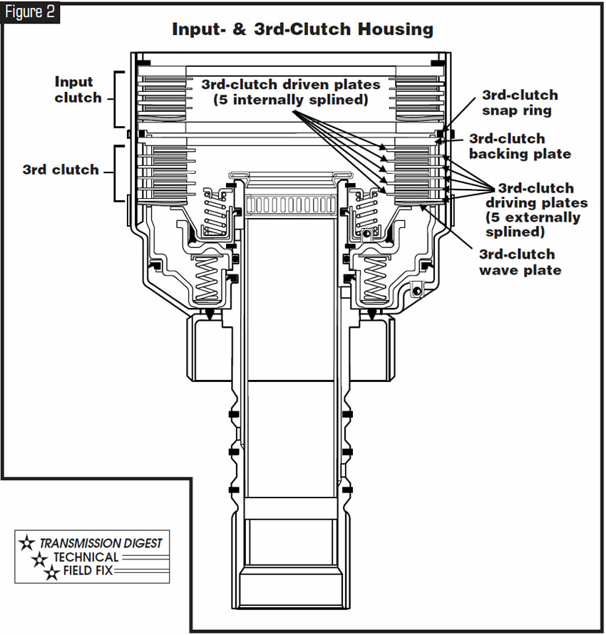
The third clutch contains five driving plates (externally splined) and five driven plates (internally splined). Each of the drive and driven plates has a friction surface on only one side. Referring to the general rule, this means that our preferred third-clutch clearance will be 0.040-0.060 inch. Each OE driving plate has a total thickness of 0.076 inch, with the steel portion of the plate measuring 0.048 inch. Each OE driven plate has a total thickness of 0.082 inch, with the steel portion measuring 0.050 inch. If the clutch clearance is 0.088 inch or more, you could remove the friction material from one extra externally splined driving plate and place the plate on top of the waved plate first and then add the regular stack of drive and driven plates.
Another possibility is substituting various-model 4T60-E or later-model 440-T4 third-clutch plates until you obtain the desired clearance. These plates are available in a variety of thicknesses. This modification will reduce the volume of oil needed to charge the clutch cylinder and cut the fill time as a result (see Figure 2).
- Thicknesses of the drive and driven plates may vary slightly with temperature.
- Do not try to eliminate the waved apply plate. If it is broken, warped or flat, replacement will be necessary.
Spacer Plate
Further modification to the valve-body spacer plate can be made to allow the second- and third-clutch cylinders to fill more quickly. Enlarging the second-and/or third-clutch feed orifices in the spacer plate by 0.010 inch will let the oil get to the cylinder faster. The original orifice size is 0.070 inch (see Figure 3).
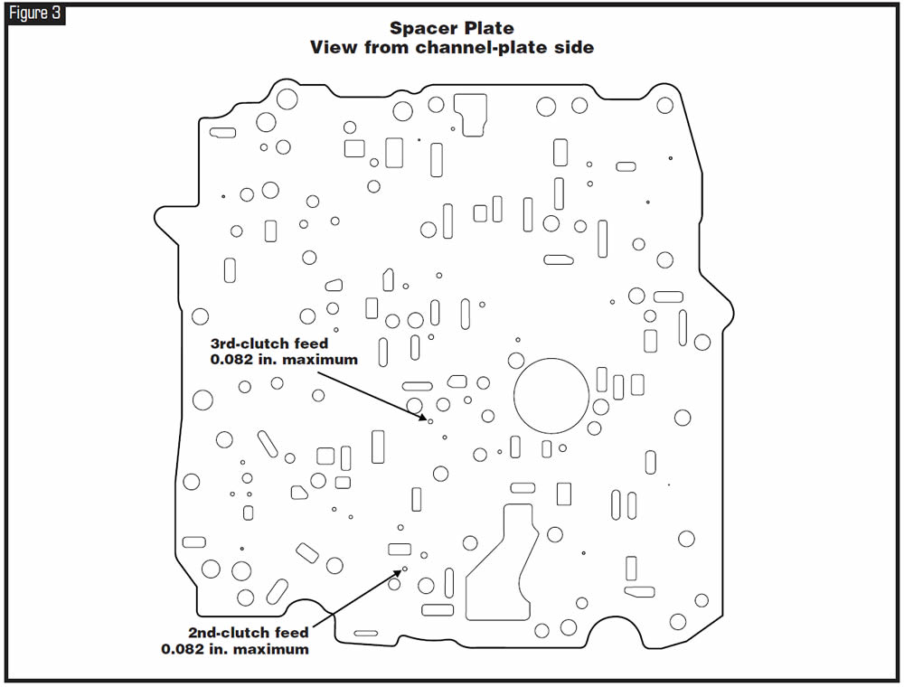
This modification of spacer-plate orifices is not recommended as a part of an overhaul procedure. It should be considered as an option only when all other possible causes have been eliminated. Do not exceed a total orifice size of 0.082 inch.


Before or after overhaul a GM or import vehicle equipped with a 4T65-E transaxle exhibits a second-gear start or is shifting out of sequence, even though a scan tool indicates that the computer commands are correct and electrical signals at the transaxle harness connector have been monitored and verified. The PCM (or TCM for some imports) may store performance codes such as P0751 (Sol. A [1-2/3-4]) or P0756 (Sol. B [2-3]).
A different complaint with the same root cause may be that the transaxle has a 1-3 shift or a 2-3 cut-loose shift when cold but operation improves as the vehicle warms up.
Mechanical problems with shift solenoids, sticking shift valves etc. are the usual and most-likely suspects.
A lack of actuator-feed-limit (AFL) oil volume or pressure to the 1-2/3-4 shift solenoid and line-pressure-control solenoid due to a damaged/mispositioned upper-channel-plate gasket, and a sticking or worn AFL valve or bore in the channel plate are commonly overlooked causes of these problems.
Disassemble and clean the entire valve body. Be sure that all valves work freely in their bores upon reassembly. If shift valves or bores are worn to the point that the valves wobble in their bore or show signs of heavy scoring as a result of contamination, replacement of the control-valve assembly will be necessary. Do not try to sand or use Scotch-Brite pads on the valves or bores.
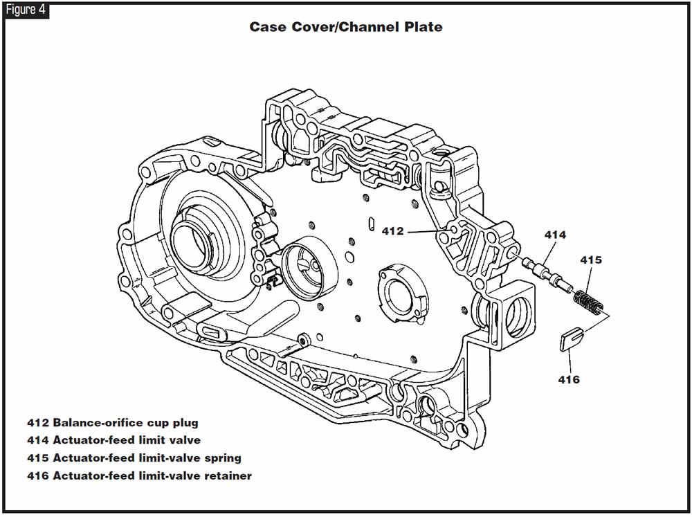
Locate the AFL valve in the channel plate (see Figure 4). Remove the retainer, spring and valve. Thoroughly clean the channel plate and valve, and inspect the valve and bore for scoring. If either the valve or bore is damaged, replacement of the channel plate will be required. Be sure the balance-orifice cup plug is present and the orifice is not plugged with debris (see Figure 4).
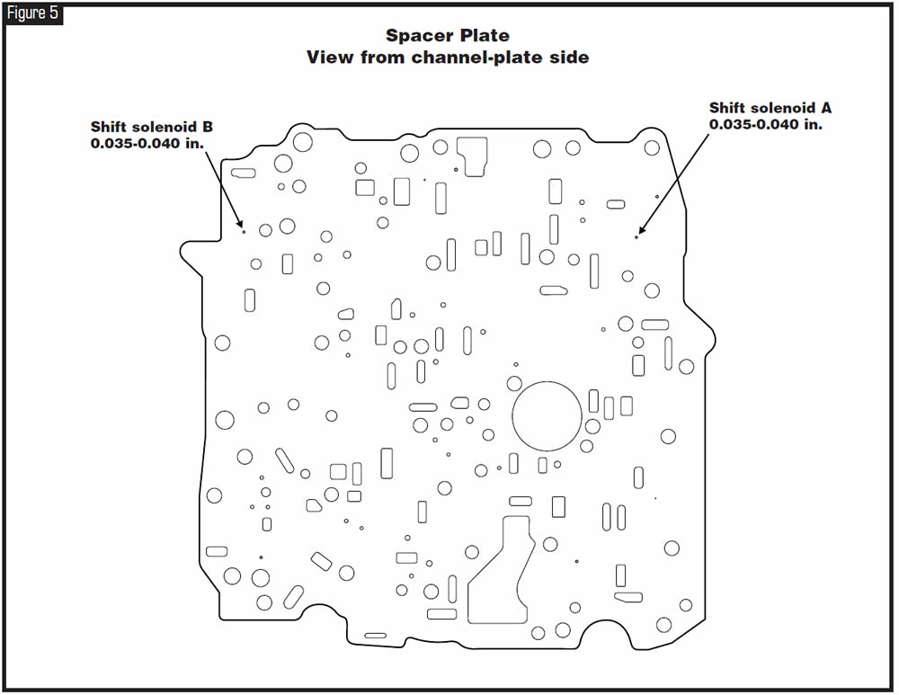
Find orifices 1 (solenoid A) and 30 (solenoid B) in the valve-body spacer plate (see Figure 5). Enlarge both of these feed holes to 0.035-0.040 inch maximum. This will help to overcome slight leakage in the feed-oil circuit. Do not exceed 0.040 inch for the feed holes or you will risk flooding the solenoids when they are open to exhaust. Clean or replace the two screens in the spacer plate. Replace both shift solenoids with new ones.

At the time of this printing the latest updated OE part number for both the 1-2 shift solenoid (A) and the 2-3 shift solenoid (B) is 24219819.


A GM or import vehicle equipped with the 4T65-E transaxle comes to the shop with a complaint of no 3-4 shift at any time.
Live data viewed on a scan tool indicates that the computer is commanding a 3-4 shift.
Shift solenoid A is being switched on after 3rd gear and the electrical signals at the trans harness connector have been monitored and verified.
The PCM (or TCM for some imports) may store a code such as P0751 for shift solenoid A performance.
The cause may be a stripped spline at the base of the fourth-clutch hub and shaft where it connects to the input sun gear (see Figure 6).

Replace the fourth-clutch hub-and-shaft assembly.
Note: Feedback received from many ATSG subscribers indicates that in most instances this problem will occur without any fault codes, such as P0751
(Shift Sol. A Performance) or P0730 (Undefined/Incorrect Gear Ratio), being stored.


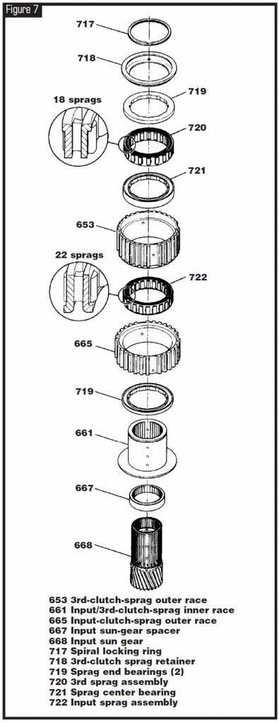
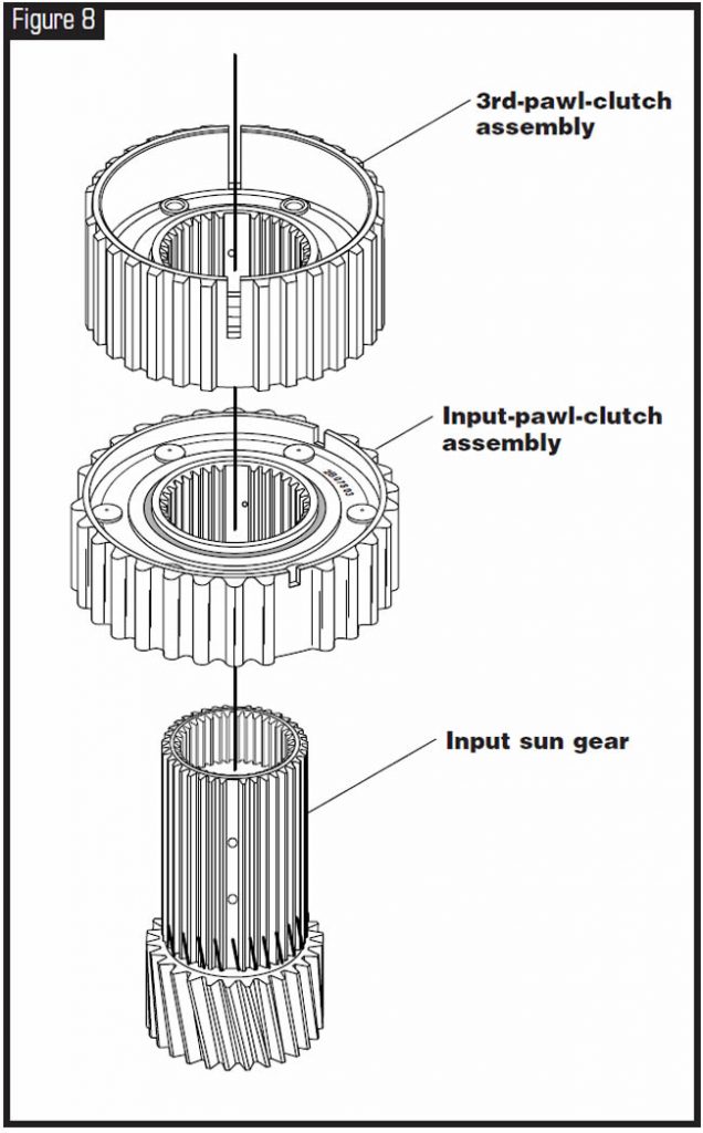
Some 2003-model THM 4T65-E transaxles will come equipped with a newly designed input and third pawl-clutch assembly instead of the previous-design input and third sprag clutch (see figures 7 and 8.) GM implemented this change at the start of production for the 2003 model year.

Ease of assembly and cost savings.

- Input pawl clutch – The new-design outer race has 30 splines instead of the previous 32 on the input sprag and cannot be disassembled like the previous-design sprag clutch, which obviously makes the assembly process easier. Refer to figures 7 and 8 for illustrations of both designs.
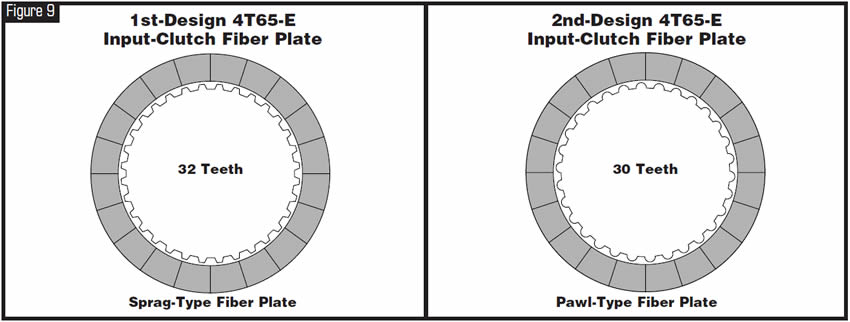
- Input-clutch fiber plate – The new-design fiber plate has 30 teeth, instead of the previous-design plate’s 32, to accommodate the new-design pawl-clutch assembly. Refer to Figure 9 for illustrations of both designs.
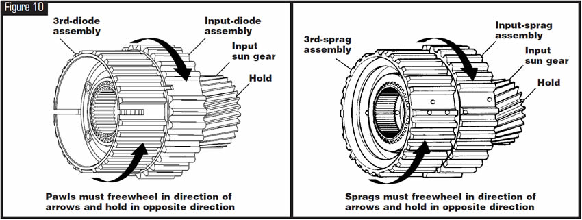
- Third pawl clutch – Unlike the previous-design sprag clutch, the new design cannot be disassembled, which obviously makes the assembly process easier. Refer to Figure 10 for illustrations of both designs. The third-clutch fiber plates remain the same as in previous models.

The parts listed will back-service any model of the 4T65-E transaxle equipped with the previous dual-sprag design when all parts are used as a service package.
Note: To maintain proper operating clearances within the transaxle, these parts must be used as a set. Do not mix these parts with any previous-design assemblies.
Component BorgWarner OEM
- Input pawl-clutch assembly . . . . . . .13013BW . . . . . . . . . . . . . .24216816
- Input-clutch friction(mates with pawl clutch) . .29194AM . . . .24216502
- Third pawl-clutch assembly . . . . . . . . .13000BW . . . . . . . . . . .24216817

May 2005 Issue
Volume 22, No. 5
- 4T65-E Transaxle: Shift Quality/Clutch Clearance
- 4T65-E Transaxle: Shifts Out of Sequence (No 1st & 4th)/Solenoid Performance Codes
- 4T65-E Transaxle: No 3-4 Shift
- 4T65-E Transaxle: New-Design Pawl-Clutch-Type Freewheel for Input and Third


