
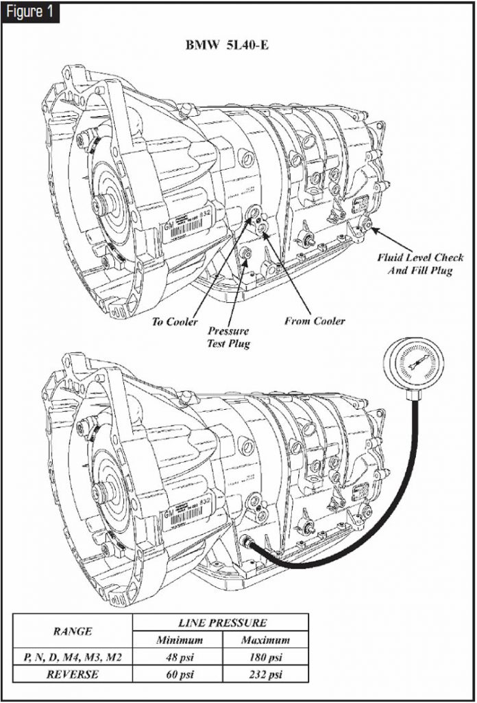
Beginning at the start of production for some 1999 models, BMW introduced a new five-speed automatic transmission (see Figure 1) that is designed and manufactured by General Motors Powertrain division in Strasbourg, France. This new transmission is designated the A5S 360R in BMW 3-and 5-series applications and the 5L40-E in Cadillac CTS applications.
The 5L40-E transmission is a completely new-design rear-wheel-drive unit and was designed to be a four- or five-speed. The same case and components are used for both applications with the exception of the 2nd clutch and the 2nd sprag clutch, and the use of a smaller Ravigneaux planetary carrier assembly in the four-speed version.
The Hydra-matic 5L40-E is a fully electronically controlled rear-wheel-drive automatic transmission with five forward speeds and a maximum torque rating of 360 N·m. It consists primarily of a four-element (lockup) torque converter, one Ravigneaux planetary gearset, nine multiple-disc friction-clutch packs, four mechanical sprag clutches and a hydraulic pressurization and control system. Figure 2 identifies the locations of the nine different clutch packs and the four mechanical sprag clutches and provides a component-application chart.
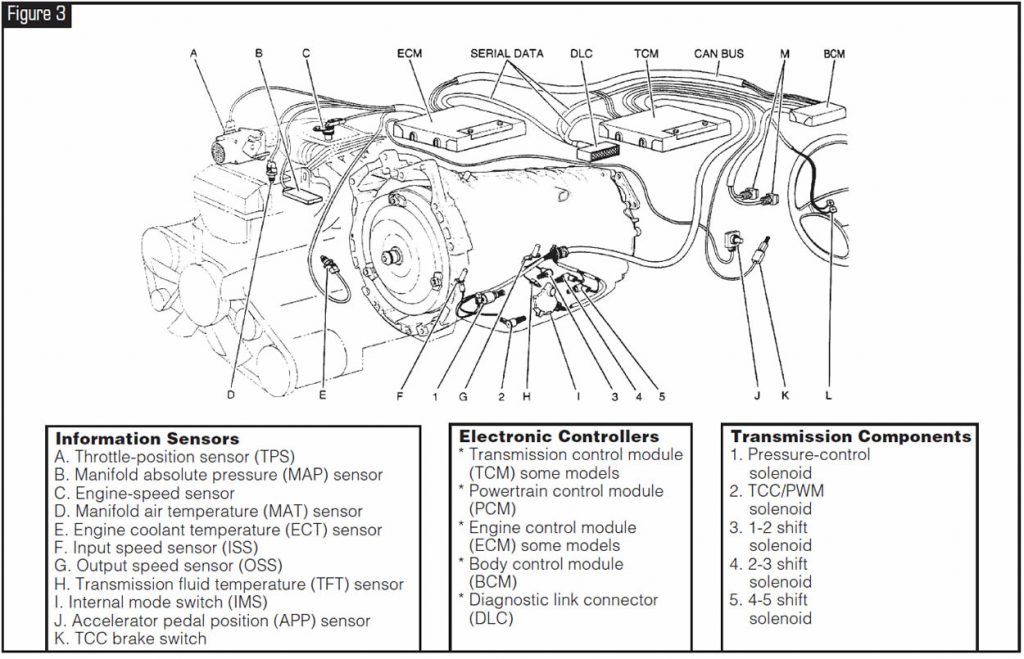
The Ravigneaux planetary gearset provides the five forward speeds and reverse. Changing gear ratios is fully automatic and is accomplished through the use of a transmission control module (TCM). The TCM receives and monitors various electronic sensor inputs and uses this information to shift the transmission at the optimum time (see Figure 3).
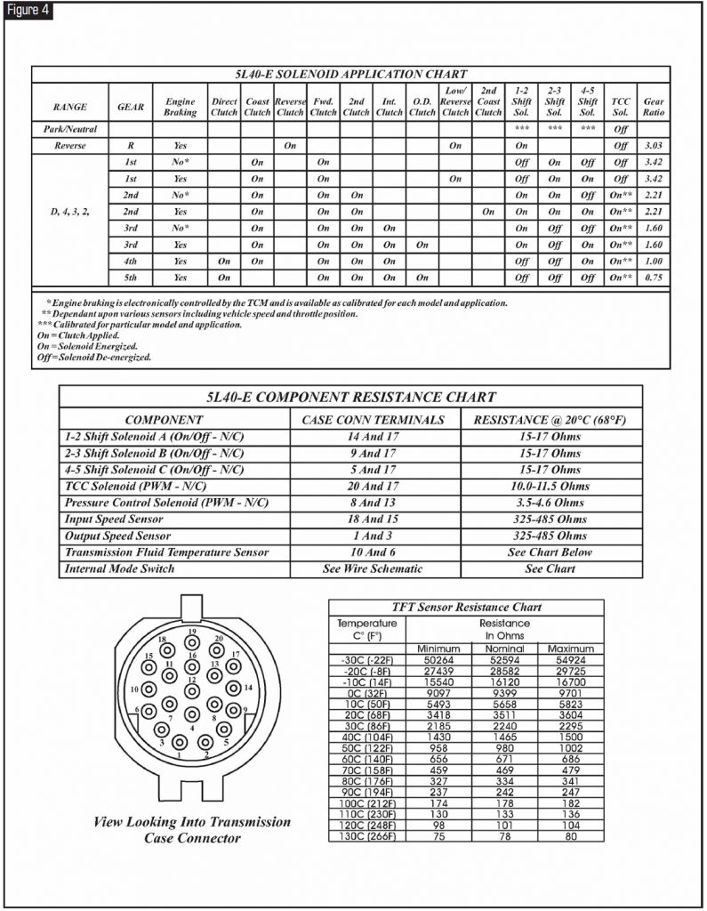
The TCM commands three on/off shift solenoids to control shift timing. The TCM controls shift feel through the pressure-control solenoid. The TCM also controls the apply and release of the torque-converter clutch through a TCC/PWM solenoid. Refer to Figure 4 for the solenoid application chart for each gear, along with case-connector pin identification and a resistance chart for the internal components.
Refer to Figure 5 for the internal wiring schematic. Notice also in Figure 5 that this transmission uses an internal mode switch (IMS).
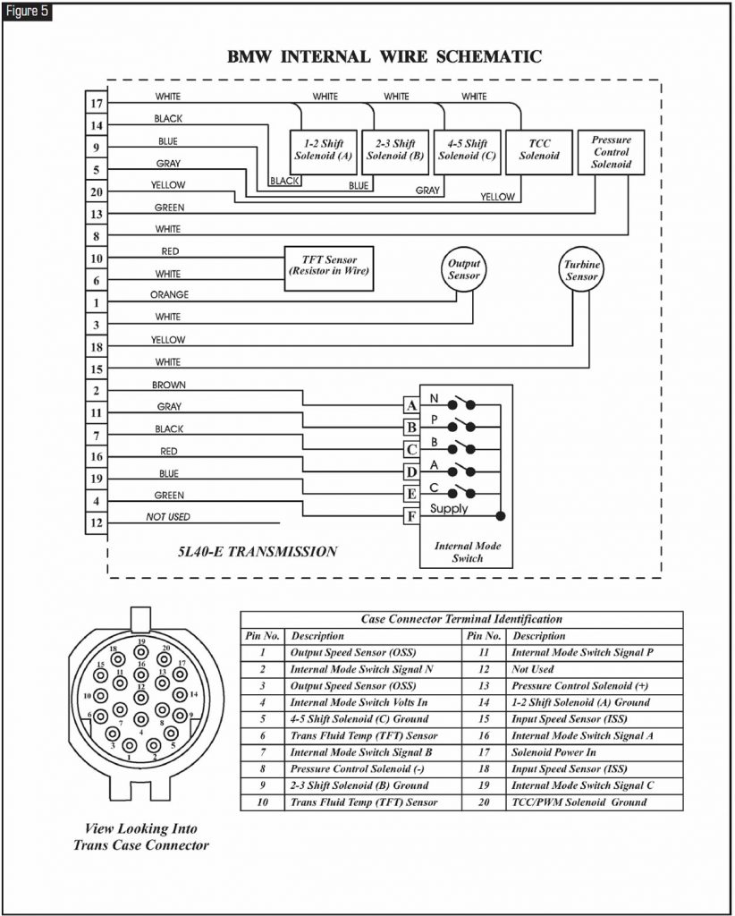
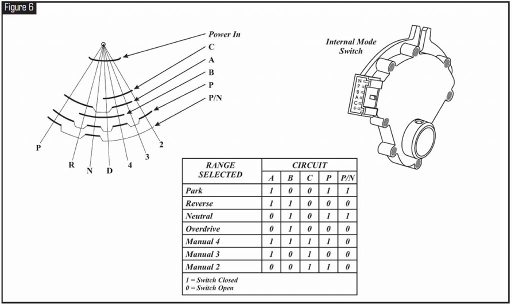
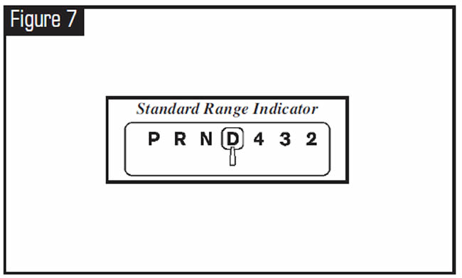
Figure 6 illustrates and explains the IMS operation, and Figure 7 provides a description of each gear range.
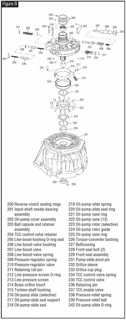
The hydraulic system primarily consists of a 13-vane pump, two control-valve bodies, two channel plates, converter housing and transmission case. The pump, illustrated in Figure 8, maintains the working pressures needed to stroke the clutch pistons that apply or release the friction components.
Figures 9, 10 and 11 illustrate the two control-valve bodies and two channel plates.
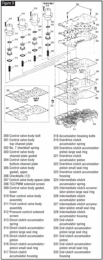
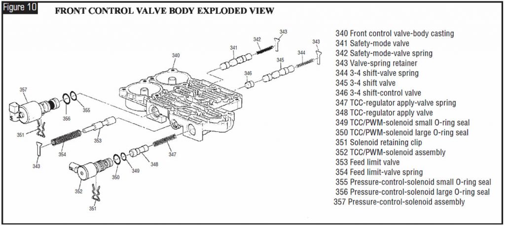
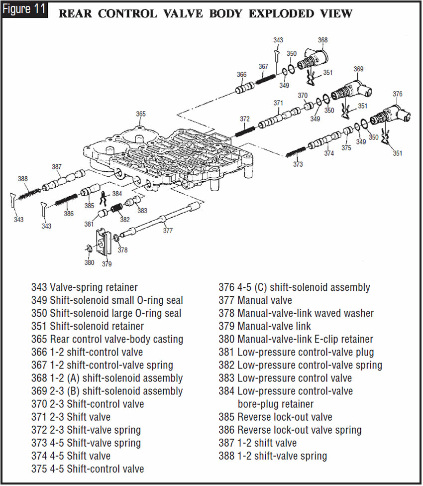
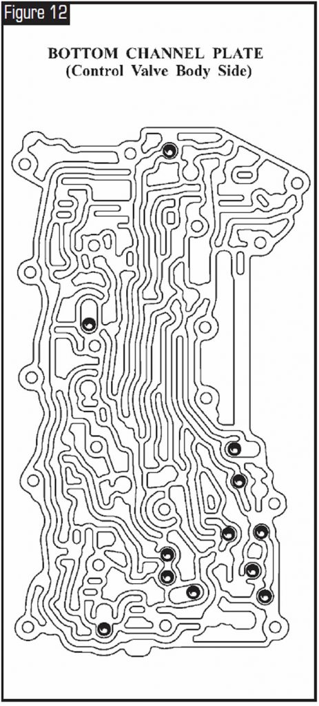
Figure 12 illustrates checkball locations for this transmission.
Electrical Components
Electrical signals from various sensors provide information to the TCM or PCM about vehicle speed, throttle position, engine coolant temperature, range-selector position, engine speed and converter turbine speed. The TCM or PCM uses this information to determine upshift and downshift speeds, apply or release of the TCC and the fluid pressure needed to apply the clutch packs. This type of control provides consistent shift points and shift quality based on the operating conditions of the vehicle.
If for any reason the entire electronic control system of the transmission becomes disabled, all three shift solenoids will be turned off. This “Safety Mode” operating state forces the transmission to operate in 5th gear when the range selector is any forward range. Also, the pressure-control solenoid is turned off, which will increase line pressure to the maximum.
Note: Some models use an engine control module (ECM) and a transmission control module (TCM), and some models use a powertrain control module (PCM) for both engine and transmission management.
Internal Mode Switch
The internal mode switch supplies the TCM or PCM with input regarding the selector-lever position (P, R, N, D, 4, 3, 2). The selector position is indicated by the state of five different on/off switches, as shown below. The mode switch is inside the transmission on the manual shaft and is fixed in rotation to the main case by the detent-lever spring, so no adjustment is ever necessary.
With the standard range indicator (see Figure 5) the transmission may be
operated in any one of the seven different positions shown on the shift quadrant:
P – Park position enables the engine to be started while preventing the vehicle from rolling either forward or backward. Park position should not be selected until the vehicle has come to a complete stop. For safety reasons, the vehicle’s parking brake always should be used in addition to the Park position.
R – Reverse position enables the vehicle to be operated in a rearward direction.
N – Neutral position enables the engine to start and operate without driving the vehicle. If necessary, this position should be selected to restart the engine while the vehicle is moving.
OD – Overdrive range should be used for all normal driving conditions for maximum efficiency and fuel economy. Overdrive range allows the transmission to upshift automatically into each of the five forward gear ratios. Downshifts to a lower gear for safe passing are accomplished by depressing the accelerator or by manually selecting a lower gear with the shift selector.
4 – Manual fourth can be used for conditions in which it may be desirable to use only four gear ratios, such as trailer towing or hilly terrain. This range is also helpful for engine braking when the vehicle is descending slight grades. Upshifts and downshifts all occur automatically, except that 5th gear is prohibited. Manual fourth can be selected at any vehicle speed, but the transmission will downshift into 4th gear only if vehicle speed is low enough not to over-rev the engine. Manual downshifts are controlled by the TCM, not the manual-valve location.


May 2004 Issue
Volume 21, No. 5
- The new GM 5L40-E (A5S 360R): Preliminary Information


