
Issue Summary:
- With all the updates on transmissions and transaxles, the interchange of parts is not as easy as it was in the past. So this month’s tech information will help in the identification of these parts and in transmission/transaxle identification.
- The information on General Motors 4T60-E covers the identification of the channel plates on models that have no manual low, plus information on the parts affected: inside detent lever, channel plate and 2nd-start switch.
- The new-design 1-2 roller clutch on the THM 4T60-E has created parts changes, along with inter-changeability and retrofit concerns.
- In a Ford AXODE (AX4S) that slips on the 2-3 shift or has no 2-3 shift, the cause may be mismachining of the direct-/intermediate-clutch cylinder or an out-of-round clutch cylinder.
- The new input-clutch retainer on Chrysler 41TE and 42LE units changed snap-ring thicknesses, and the reaction plate was modified.
- Chrysler A500/42RE series transmissions may have no reverse or a bind-up on the 3-4 shift because of a mismatch of the overdrive-/direct-clutch housings, depending on engine size and transmission model.


Beginning at the start of production for 1994-model vehicles, some 4T60-E transaxles were produced with a unique six-position inside detent lever and a unique channel plate that eliminates the manual-low position on the indicator.

To allow installation of four-speed transaxles in vehicles that used the three-speed shift linkages and previously were equipped with THM 125C transaxles.

- (1) Inside Detent Lever – Stamped with six positions for the detent spring instead of the current seven positions (Figure 1). This eliminates the manual-low position. Part numbers stamped on the detent levers will help in identification.
- (2) Channel Plate – New casting that incorporates the manual-1st and manual-2nd cavities. The two channel plates have different casting numbers for identification (Figure 1).
- (3) 2nd-Start Switch – Most of the vehicles using the six-position detent lever also will have a 2nd-start switch on the instrument panel. When depressed, the switch will allow the vehicle to start off in second gear to provide additional traction.
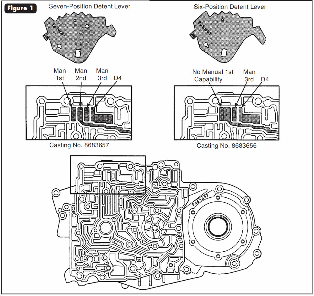

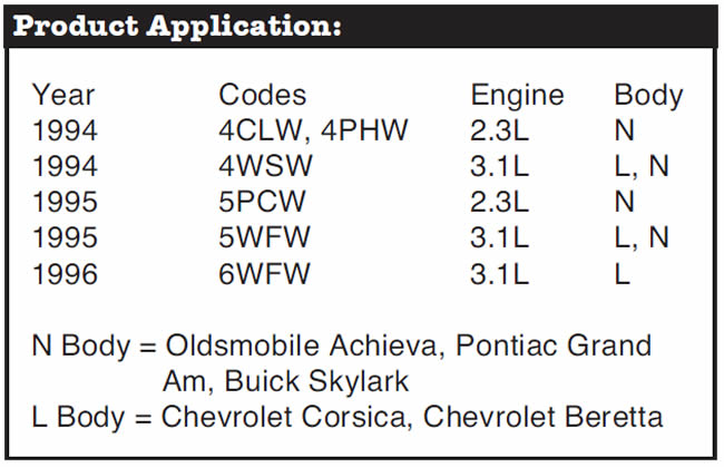
None of the parts listed will interchange with those from models with the seven-position detent lever. The six-position inside detent lever must be used with the channel plate that has casting number 8683656, and the seven-position inside detent lever must be used with the channel plate that has casting number 8683657 (Figure 1). We have provided the models, engine sizes and transaxle codes for vehicles that used the six-position detent lever in production. Refer to the accompanying chart.


Beginning at the start of production for 1996 models, all THM 4T60-E transaxles were built with a new-design 1-2 roller-clutch assembly (Figure 2).
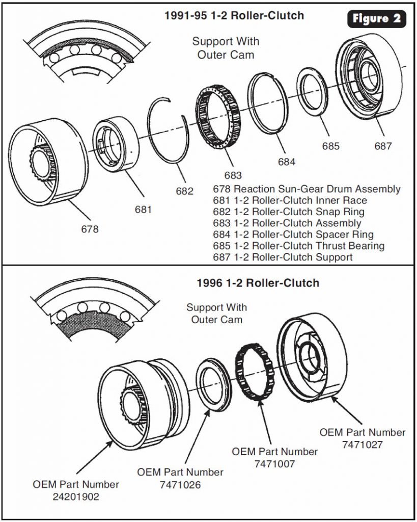
Eliminates a potential high-speed freewheel failure and reduces the number of parts needed for the assembly process.
- (1) 1-2 Roller-Clutch Support – Roller-clutch cam is now the inside-diameter design instead of the previous outside-diameter design, and the bushing that supports it on the final-drive ring gear has doubled in width for much-improved stability of the 1-2 roller-clutch support. See Figure 2 for illustrations.
- (2) Thrust Bearing – Dimensional changes to accommodate the new-design 1-2 roller-clutch support (See Figure 2).
- (3) 1-2 Support Spacer – Eliminated, as shown in Figure 2.
- (4) 1-2 Roller-Clutch Assembly – Dimensional changes to accommodate the new parts of the 1-2 roller clutch with inside-diameter cam design, as shown in Figure 2.
- (5) 1-2 Roller-Clutch Snap Ring – Eliminated, as shown in Figure 2.
- (6) 1-2 Roller-Clutch Inner Race – Eliminated, as shown in Figure 2.
- (7) Reaction Sun-Gear Drum – Redesigned with the 1-2 roller-clutch outer race now made as part of the sun-gear drum, to accommodate the new-design 1-2 roller-clutch parts, as shown in Figure 2.
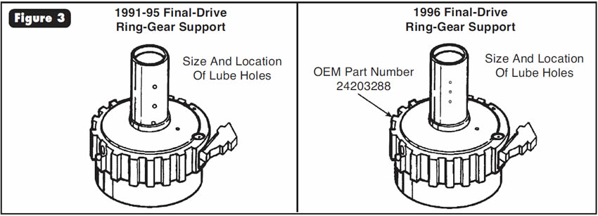
- (8) Final-Drive Ring Gear – Revised lubrication-hole sizes and locations in support to accommodate the new-design 1-2 roller-clutch assembly, as shown in Figure 3.
The new-design 1-2 roller-clutch assembly will back-service all THM 4T60-E transaxles to 1991; however, all parts listed must be used as a package.
Special Note:
The Sonnax 1-2 Roller Spring Kit is highly recommended for 1991-95 models to eliminate a condition of roller-clutch destruction during freewheel. The Sonnax kit will not fit and is not needed for the 1996-up models, as the updated parts listed eliminated the problem.


Before and/or after overhaul, some ’96-97 Tauruses, ’96-97 Sables and ’96-97 Windstars exhibit a flare or slipping condition on the 2-3 shift, or no 2-3 shift.

The cause may be a mismachined direct-/intermediate-clutch cylinder, as shown in Figure 4, or the direct-clutch steel plates binding in the clutch cylinder because of the cylinder being out of round.
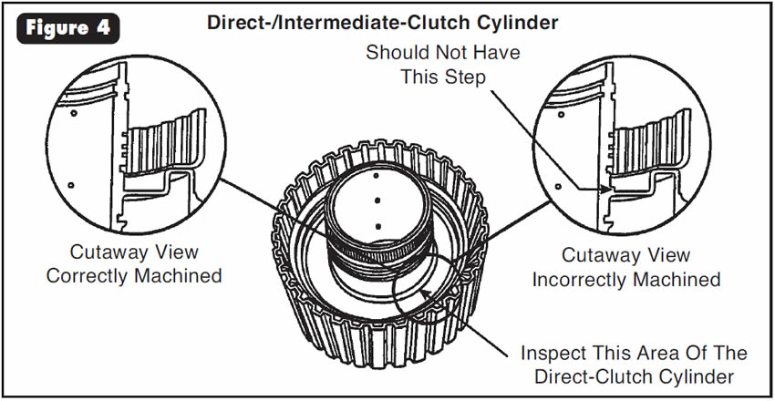

Inspect the direct-clutch-cylinder hub machining in the area shown in Figure 4, and replace the clutch cylinder if necessary. Check for free movement of the steel clutch plates in the direct-clutch cylinder by installing and removing the plates, turning the plates 2-3 splines each time. Replace the direct-clutch cylinder if necessary.
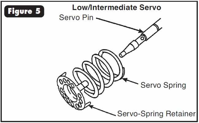
Also, the three tabs on the servo-spring retainer must fit on the outside edge of the spring, as shown in Figure 5. Replace the servo-spring retainer if it is bent or damaged from an incorrect installation.

- Direct-/Intermediate-Clutch Cylinder (3.0L Taurus) . . . . . F6DZ-7G120-A
- Direct-/Intermediate-Clutch Cylinder (3.0L SHO Taurus) . . . . . . . . . . F3DZ-7G120-A
- Direct-/Intermediate-Clutch Cylinder (3.8L Windstar) . . F68Z-7G120-BA
- Servo-Spring Retainer (All Models) . . . . . . . . . . . . . . . . F0DZ-7G151-A

A running change for 1996-model 41TE and 42LE transaxles was the introduction of thicker snap rings inside the input-clutch retainer.
Increased durability.
- (1) Input-Clutch Retainer – The snap-ring grooves in the input-clutch retainer that are used to hold the UD/OD reaction plate in place changed dimensionally to accommodate the thicker-design snap rings. Originally, 1989 input-clutch retainers carried three overdrive frictions. The tapered snap ring used on top of the reaction plate measured 0.070 in. thick. In 1990, the retainer was redesigned to accept a fourth overdrive friction plate. The tapered-snap-ring groove in the UD/OD reaction plate was moved down by 0.040 in. to make room for the added lined and steel plates. At this time the thickness of the tapered snap ring was decreased to 0.060 in. (See Figure 6).
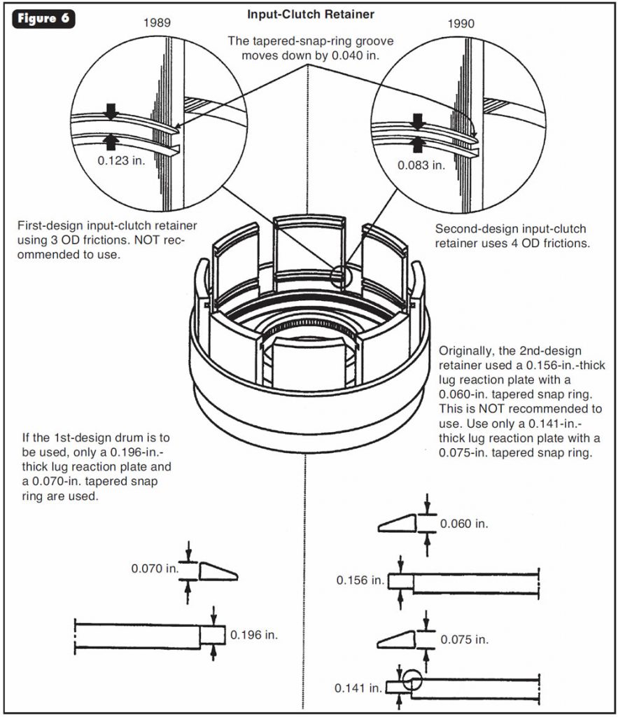
- To distinguish first-design and second-design retainers, measure the distance between the snap-ring grooves as shown in Figure 6. If the distance is about 0.123 in., the retainer is designed for three overdrive clutches. If the distance is about 0.083 in., the retainer is designed for four overdrive clutches. Soon after this change occurred, the tapered snap ring was breaking more frequently. In an attempt to resolve the problem, GM increased the thickness of the tapered snap ring to 0.075 in. No dimensional changes took place with the input-clutch retainer. However, the reaction plate received a relief cut across the top of the lug to make room for the installation of the thicker snap ring, as shown in Figure 6.
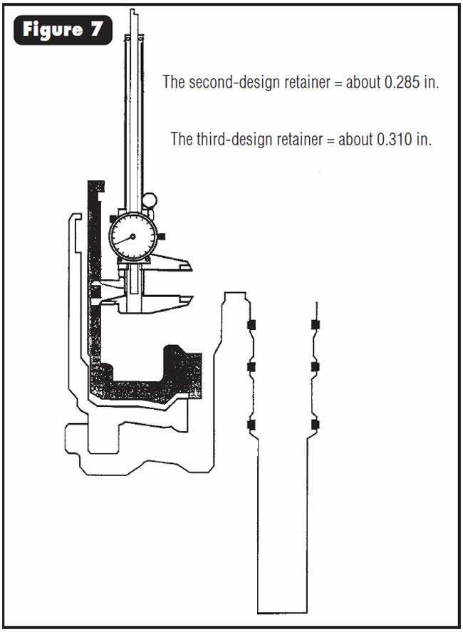
- The running 1996 change increased the thickness of the tapered snap ring again and, for the first time, the lower flat snap ring. To accommodate this change, the upper and lower snap-ring grooves had to be widened to accept the thicker snap rings. To distinguish second-design and third-design retainers, measure the snap-ring grooves from outer edge to outer edge, as the distance between the grooves did not change (See Figure 7). The measurement on the second-design retainer will be about 0.285 in. On the new third-design retainer with the thicker snap rings, the distance will be about 0.310 in.
- (2) The Flat UD/OD Reaction-Plate Snap Ring – The thickness of the flat snap ring under the UD/OD reaction plate increased from 0.060 in. to 0.075 in.
- (3) The Tapered UD/OD Reaction Plate Snap Ring – The thickness of the tapered snap ring on top of the UD/OD reaction plate increased from 0.075 in. to 0.090 in.
- (4) The UD/OD Reaction Plate – The UD/OD reaction plate received a larger relief cut across the top of the lug to make room for the installation of the thicker snap ring, as shown in Figure 8.
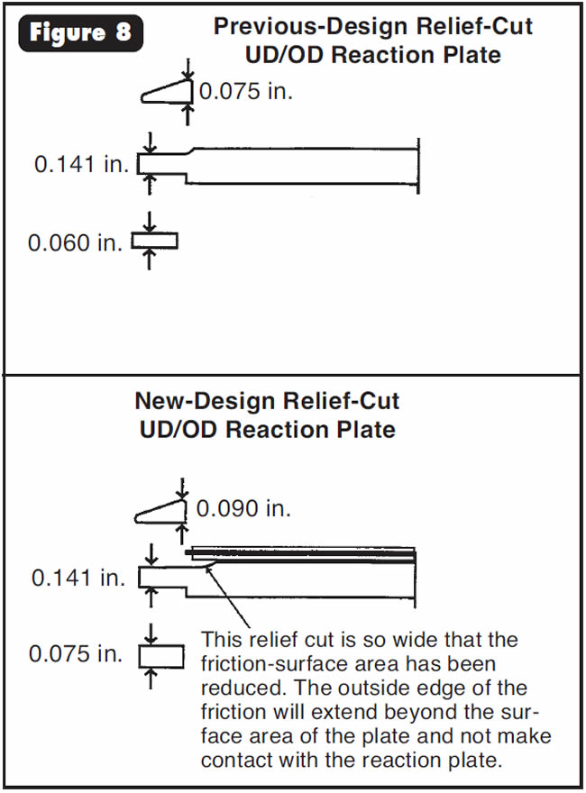
Note:
This relief cut is so wide that the friction-surface area has been reduced. The outside edge of the friction will extend beyond the surface area of the plate and not make contact with the reaction plate.
- Input-Clutch Retainer………………………..04886300AA
- Includes the retainer, both snap rings and two reaction plates for UD-clutch clearance.

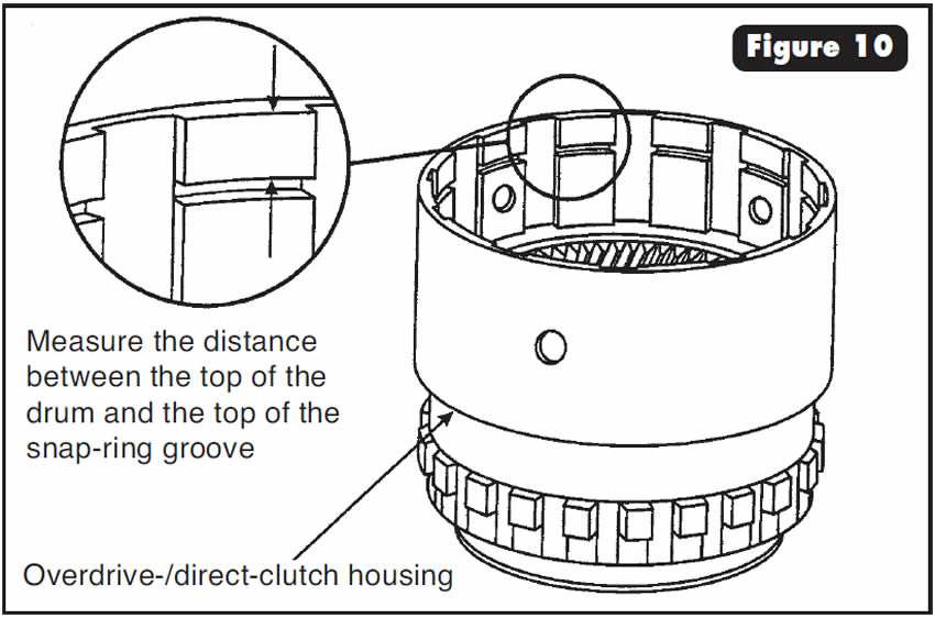
After rebuild, either there is no reverse or there is a bind-up on the 3-4 shift.
One cause may be incorrect assembly of the overdrive direct clutch. Steels and pressure plates of two different thicknesses are available, and not knowing the difference can result in incorrect assembly of the pack.
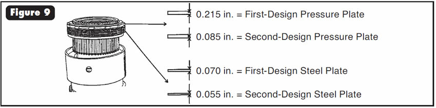
- Step 1: Identify the top pressure plate you are using by measuring the lug thickness. The lug thick-ness on the first-design pressure plate is about 0.215 in. On the second-design pressure plate, the lug is about 0.085 in. thick (See Figure 9).
- Step 2: Identify the steel plates you are using. The first-design steels are about 0.070 in. thick, and those used with the second design are about 0.055 in. thick (See Figure 9).
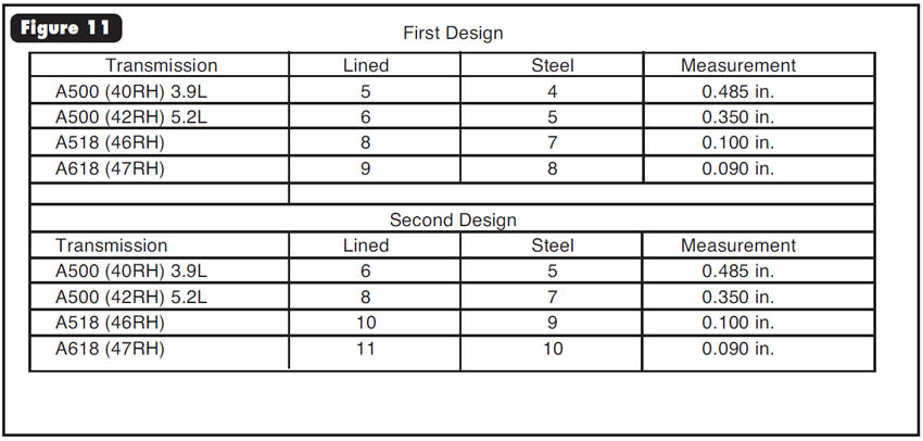
- Step 3: If all first-design steels and pressure plate are being used, use the chart in Figure 10 to identify the overdrive-/direct-clutch drum you have and the number of clutches and steels needed for that drum. If all second-design steels and pressure plate are being used, use the chart in Figure 11 to identify the overdrive direct-clutch drum and the number of clutches and steels needed for that drum.
Special Note:
Always measure to determine the correct thickness for the overdrive-piston shim. An incorrect shim also may cause the complaint mentioned at the beginning of this section.
- 0.085-in. pressure plate …………………………4461183
- 0.055-in. steels ………………………………..4864053
- 0.215-in. pressure plate …………………………4461031
- 0.070-in. steels ………………………………..4461054

May 2000 Issue
Volume 17, No. 5
- THM 4T60-E: Channel-Plate Identification for Models With No Manual Low
- THM 4T60-E: New-Design 1-2 Roller Clutch
- Ford AXODE (AX4S): Slip on 2-3 Shift and/or No 2-3 Shift
- 41TE and 42LE: New Input-Clutch Retainer
- Chrysler A500/42RE Series Transmissions: No Reverse, or Bind-up on the 3-4 Shift


