

The transmission repair industry has always been afflicted with change, involving some decades more than others; however, transmission variations occurring over the past 15 years or so have made previous change pale in comparison. From a variety of traditional step-type trans-missions to several models of CVTs to a few versions of EVTs, there has been a lot to contend with and more to come.
Another transmission format that is gaining traction not only overseas but here in the states is a blending of the old standby manual shift transmission and portions of automatic transmissions, which is the DCT (dual-clutch transmission). The gearing in a DCT is vintage manual-shift transmission design including synchronizers and shift forks. The difference is that the shift forks are computer-controlled hydraulically or electrically operated and the input is provided by an automated clutch assembly. A wet DCT uses normal looking automatic transmission clutch packs; whereas a dry DCT uses a modular dual-clutch plate standard shift design. Who knows which transmission platform will win out.
The premise behind a DCT is that it has more precise upshifts and downshifts than a regular automatic transmission. Before the shift is felt by the driver, the gearing of the transmission actually changes and is already in the proper position awaiting the dual-clutch assembly to transition from one clutch pack to the other, which ultimately drives a solid or hollow input shaft. The clutch pack transition is what the driver feels, not the movement of the shift forks or synchronizers that makes the shifting of a DCT crisp. This may score points in a lab environment, but how much a DCT shift differs from a normal automatic transmission is the question.
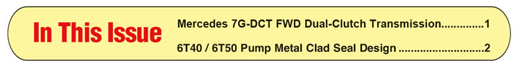
Mercedes, which has always been a hard-core rear-wheel-drive step-type transmission car company apparently, felt the DCT had merit due to the fact that it launched its own version in late 2011. Unlike other car companies that have adopted the DCT technology, but preferred to outsource the units from other transmission manufacturers, Mercedes actually developed and produced the 7G-DCT (724.0) internally. Models A class and B class, among others, that are FWD with smaller engines will most likely be equipped with the new seven-speed DCT. Although currently more popular in Europe, there are some here in the states with more to come. An easy way to identify the new unit is by the combination remote cooler/external filter assembly mounted on top of the case (Figure 1).
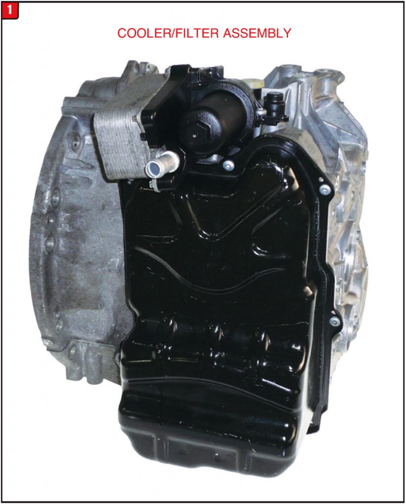
The 7G-DCT is a two-piece design unit with a bell housing and main case section. There is no end cover but merely a couple of end caps with molded rubber that fit into the case. The valve-body cover is metal and uses a removable gasket between the case and once removed will expose the valve body and filter assembly. Unlike many other FWD transmissions of this nature that requires removal and disassembly to gain access to the filter, Mercedes designed the 7G–DCT to be able to service the filter by removing the valve body cover only (Figure 2).
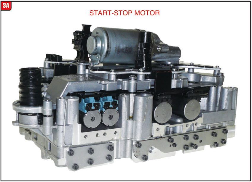
Valve body: All later model transmissions contain valve bodies that are rather involved and the Mercedes 7G-DCT is no exception. In addition to having a lot of stuff, the valve body is a mechatronic design meaning that it has an internal TCM (Figure 3A).
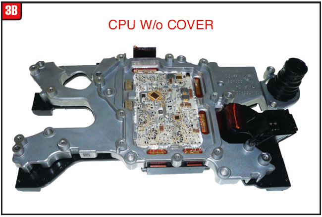
There are three main chunks of the assembly, one of which is the TEHCM unit (Figure 3B). The electrical case connector attaches directly to the TEHCM and extends through the main case section. The CPU cover has a rubber seal to prevent transmission fluid from leaking in and is attached to the body by a fixed electrical ribbon.
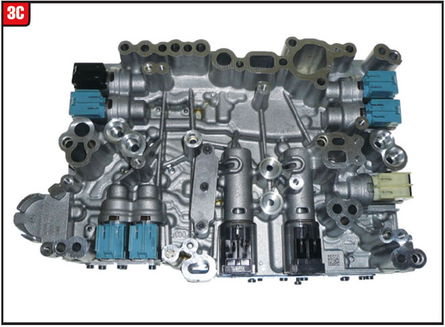
On top of the main valve-body section is a relatively new feature that more transmissions are being designed with, which is a start-stop motor/pump assembly. A start-stop pump assembly can be attached to a variety of places depending on manufacturer, however Mercedes chose to connect it directly to the valve body. Beyond the start-stop pump unit are nine solenoids, some linear and some on-off (Figure 3C). Always mark all solenoids prior to removal for proper reassembly in order to avoid calibration issues.
Park unit: A relatively important aspect of any transmission is the park assembly, and although minimal attention is devoted by technicians to the design and operation, the assembly must function well or big problems will occur. There are some newer model transmissions that deviate from the normal manually operated park mechanism and the 7G-DCT is certainly one of them. The park assembly consists of a hydraulic/electronic unit that is rather compact (Figure 4). One of the two end caps at the back of the main case section covers the park unit. The valve body must be removed along with the end cap to remove the park unit.
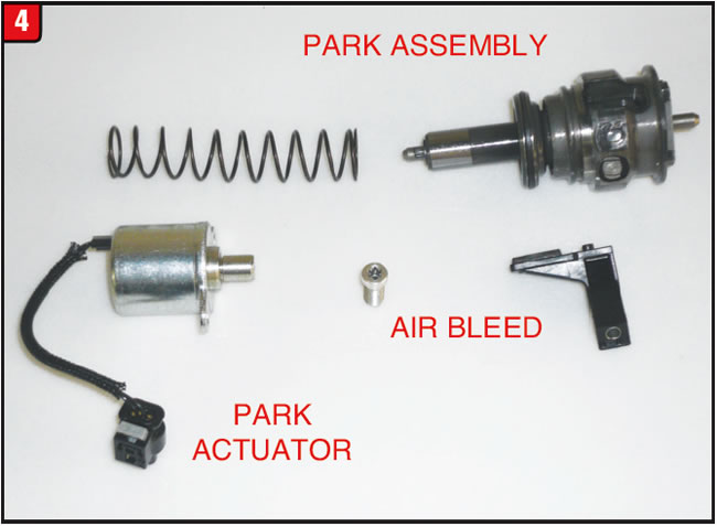
The assembly contains a piston that is hydraulically operated to engage and release the park pawl and is fed directly from the valve body. In addition to hydraulic operation is a park actuator motor that is located under the valve body, which is operated by the TCM. There is also a plastic bracket that bolts to the piston assembly, which contains a magnet that signals the TCM as to the park piston position. The assembly must be rotated counterclockwise to enable removal because of the park pawl. The assembly is also spring-loaded.
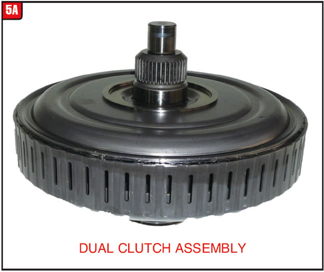
Dual-clutch assembly: The basis of any DCT is the dual-clutch assembly, which is accessible once the front cover is removed. The front cover is like a metal-clad seal which seals at the OD and ID just like a metal clad, only much larger. The dual-clutch assembly is a rather compact unit that merely has an input shaft stub that splines to a damper plate (Figure 5A). The backside of the assembly contains the sealing-ring tower that extends into a steel sleeve in the bell housing. Also mounted on the backside of the housing is a remote axis pump drive gear.
Each manufacturer that produces a DCT uses a particular method for assembling the clutch. Unfortunately, when Mercedes designed the 7G-DCT, it chose to weld the input flange to the housing, which means the assembly has to be cut apart on a lathe and then re-welded later on. To make matters worse the K1 (large diameter clutch) piston is not removable without hacking the housing to pieces. The K2 bonded piston is accessible. As a practical matter, it is probably best to purchase the entire dual-clutch assembly, at least until other options are developed.
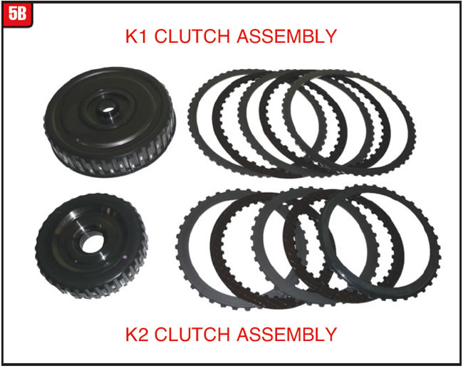
Internally, the Mercedes unit resembles most other dual-clutch assemblies. There is a large and small clutch pack that drives the adjacent clutch hub (Figure 5B). The large clutch hub splines to and drives the solid input shaft, whereas the small clutch hub with the larger bore splines to and drives the hollow input shaft. The 7G-DCT uses four frictions and steels for each clutch pack assembly.
Remote axis pump: In an effort to squeeze out every bit of horsepower, manufacturers have taken steps to reduce the demand on engines for some time now. One trend that has taken hold is to no longer have a direct drive pump (one directly driven by the engine) but rather switch to a design that entails a ratio-type drive. The remote axis pump certainly meets the OEM requirements, in that it can be placed at several different positions as well as being driven at different speeds relative to engine speed. The pump itself can be chain driven or gear driven based upon need.
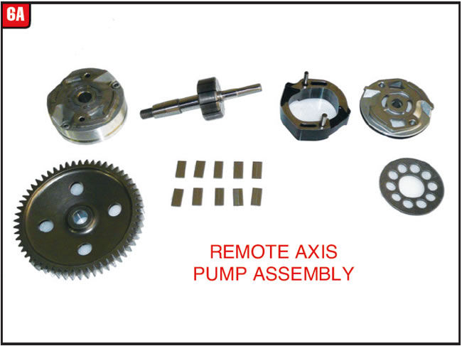
With the dual-clutch assembly out of the way, the bell housing can be unbolted and removed from the case. The gear-driven remote-axis pump is now accessible and sets into a pocket in the main case section. The pump itself is designed like many other pumps of that type (Figure 6A).
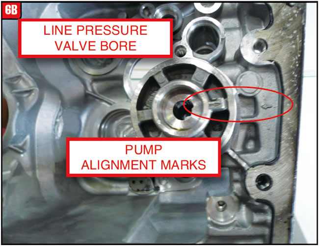
One aspect that is unique is that there is a left-handed nut that retains the pump-driven gear to the pump shaft and the shaft and gear bore are tapered, which means they will not fall off. Pay special attention to the position of the pump slide during removal. One other item to note is the position of the front cover which must be rotated correctly. To make sure that it happens there is an arrow cast into the front cover as well as into the main case section (Figure 6B). There is also a beveled plate that goes between the end cover and case to keep all the pieces squeezed together.
Directly above the pump is a hole in the case that contains a high-pressure relief valve and spring assembly. Note the position of the valve and spring to avoid installing them backward.
Main gearing: In addition to two different input shafts, there are two different output shafts both of which are capable of driving the differential carrier and at different ratios. For illustration purposes all gear components are positioned onto the bell housing (Figure 7). The 7G-DCT uses RTV between the bell housing and case sections due to the tapered roller bearing preload concerns. During disassembly note the bonded rubber pressure seal that goes between the bell housing and case. Underneath the bearing races are selective shims for each shaft assembly. There are also two large plastic oil baffles that go on each side of the differential carrier.
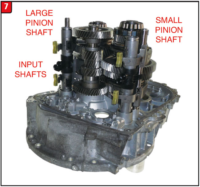
Each output (pinion) shaft contains a specific amount of gears to provide the seven forward speeds and reverse. One shaft uses gears for 1st, 2nd, 4th & 5th speeds while the other shaft contains gears for 3rd, 6th, 7th & reverse. Gears on both a solid and hollow input shaft correspond to the respective gears on the outputs. The fork assemblies, which are hydraulically operated, are contained within two steel tubes that are positioned between apply holes in the bell housing and case. There is one component common to most manual shift transmissions that is not in illustration 7 because it is not used, which is a separate reverse idler gear. Reverse is achieved in a different manner that was done to other models.
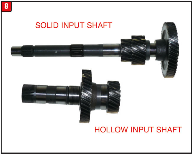
Input shaft: A DCT is basically two transmissions blended into one and it is the dual input shaft that makes it possible. As with other models of DCT there is a solid and hollow input shaft which connects to all of the output gears (Figure 8). Each input shaft is driven by its respective clutch-pack assembly and is responsible for odd and even gear ratios. The solid input shaft is responsible for odd numbered gears and the hollow input shaft is responsible for even number gears plus reverse. Both shafts are supported by ball and needle bearings.
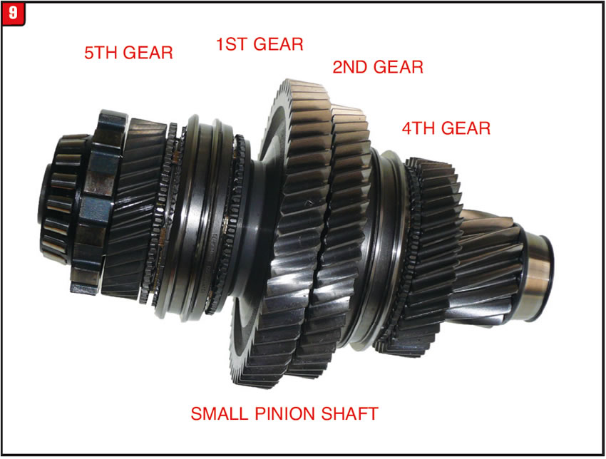
Output shaft (small pinion gear): The two output-shaft assemblies contain different stuff but basically function the same. The small pinion gear output shaft has tapered roller bearings on each end for support and includes the park gear (Figure 9). There are four drive gears (1st, 2nd, 4th & 5th) along with the small pinion gear mounted onto the output shaft. In addition there are two synchronizer assemblies that connect to the gears, which is a fairly common design.
Output shaft (large pinion gear): Although the small pinion gear shaft assembly is fairly traditional, the large pinion gear shaft is not. At first glance the two shafts look similar in that they both use four drive gears, one pinion gear and have tapered roller bearings at each end (Figure 10). Where the difference lies is that this shaft has three synchronizer assemblies that are not traditional. The design has to do with the reverse-gear operation. As stated, there is not a reverse idler gear used in this transmission because the manufacturer has found another method.
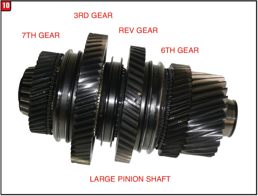
Basically reverse is accomplished by the hollow input shaft driving second gear, which also meshes with the reverse gear on the large pinion output shaft. The third (extra) synchronizer that is positioned between reverse and third gears connects the two together and third gear is then anchored to the output shaft via the 7th gear/synchronizer, which is driven backwards. It is a pretty slick design.
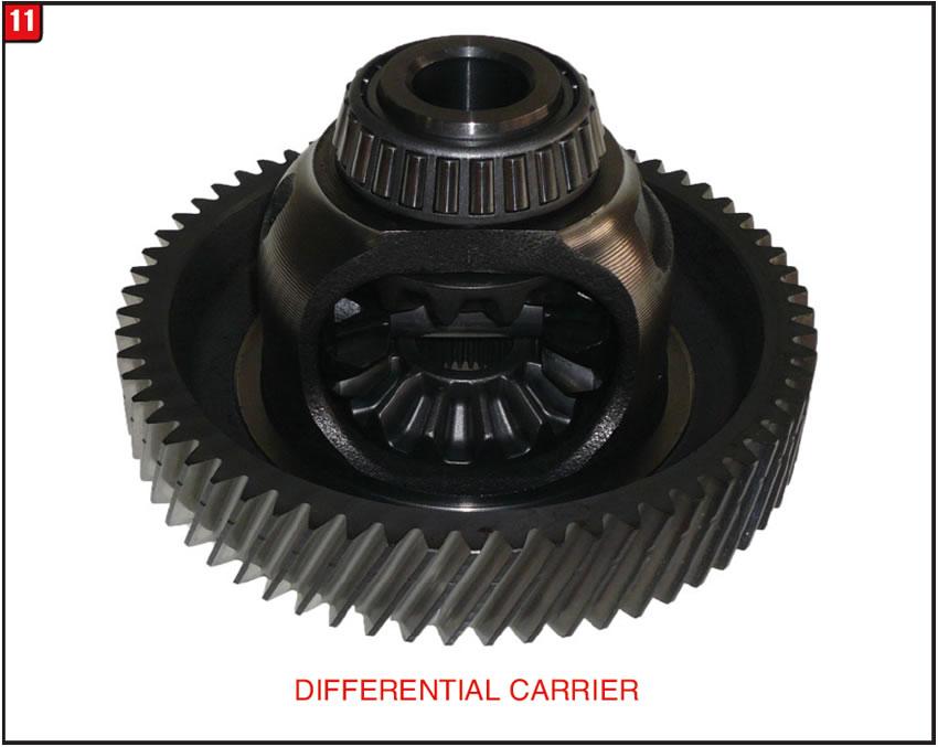
Differential assembly: The differential used in the 7G-DCT is a common type assembly used on many front wheel drive transmissions (Figure 11). It also uses tapered roller bearings for support and has regular style spider gears with the main difference being that it is driven by two output shafts instead of one.
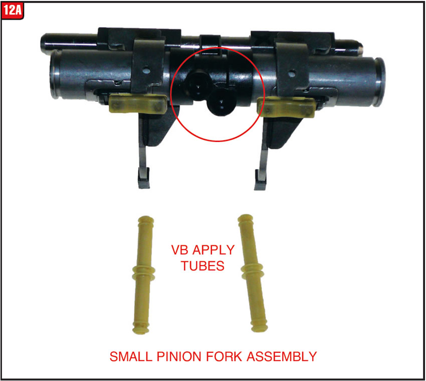
Shift fork assemblies: The shift forks that provide all the gear changes are hydraulically operated and are fairly compact. The apply pistons used to move the forks back-and-forth are the same type used in the VW 02E DCT. The shift fork apply tab is positioned within a long steel tube that goes in between the bell housing and case. There is an O-ring at each end of the tubes that seal against the oil bores of the housings. The tubes also contain the detent mechanism for each fork for proper positioning. Each fork has a plastic tab that contains magnets which signals the TCM as to the fork position. Everything is aligned by long steel rods that also go between the bell housing and case. There are two small plastic tubes that extend from the valve body to the metal fork tubes that contain O-rings at each end.
The fork assembly for the small pinion output shaft has two shift forks (Figure 12A). With everything removed from both long metal tubes, they may appear to be the samel; however, they are not. There is a slight difference in the length of the valve-body oil tube holes with the small pinion shift-fork assembly tube being the shorter of the two.
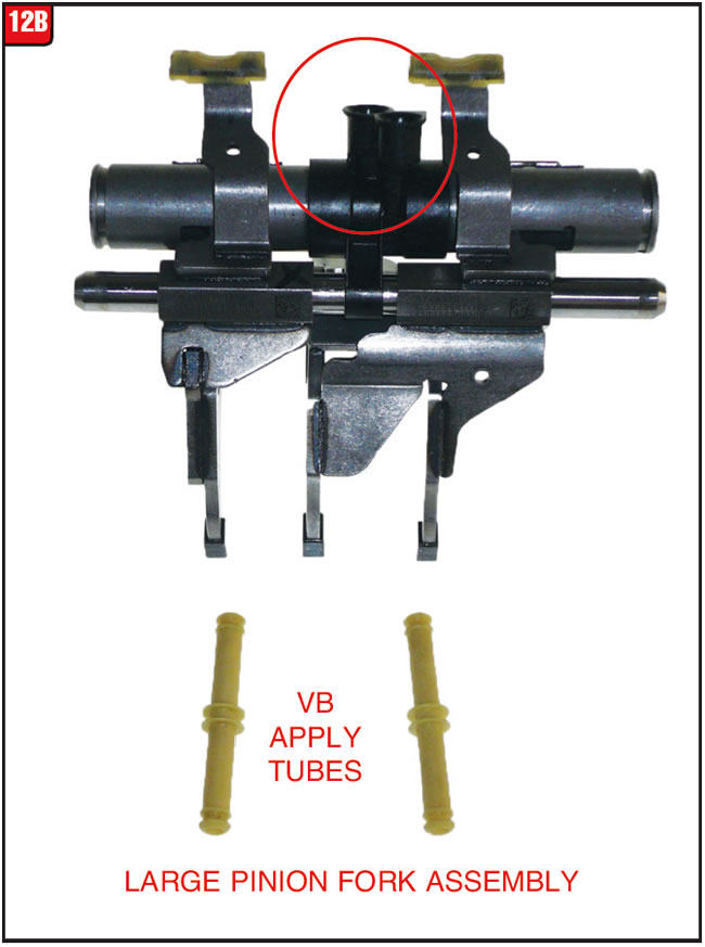
The large pinion-shaft shift fork assembly is the one that contains three shift forks (Figure 12B). Construction and operation are pretty much the same between the two assemblies with the exception of the third shift fork. The third fork is actually connected to one of the other two forks to form one unit meaning that when it moves two synchronizer sleeves also move for reverse or third gear.
As with any new transmission design it takes a bit of effort to get up to speed as to operation and repair, not to mention product acquisition. The Mercedes 7G-DCT is no exception just more opportunity.
Special thanks to the product specialists at TransTec for providing the transmission illustrated in this article and related product information. An overhaul set by TransTec will be available in the near future.


Disparities have existed between common components of a given transmission almost from day one, with some more pronounced than others. Much of the time after a transmission is launched and some type of upgrade occurs it’s no big deal, whereas there have been instances when an upgrade or minor tweak is implemented that it does becomes a major hassle.
Usually when one of these upgrade nightmares happens, it involves some type of major hard part or even an electrical item but not always. Such is the case concerning the pump metal-clad seal for a GM 6T40 and 6T50 transmission family. When the front-wheel-drive six-speed automatic was released, the pump contained a rather conventional type of metal-clad seal for the torque converter hub. GM apparently had a concern that the seal could pop out of the pump body because it was designed to be held in place by a snap ring.
It is rather amazing though that when Ford released the 6F35 there was no snap ring to hold the pump seal in place; however, beginning in 2012 someone made a decision that one was needed because the pump and metal-clad seal were redesigned to accommodate a snap ring, just like GM – go figure.
Not to be outdone when it comes to change GM decided to make a minor tweak to the 6T40 although not for the regular models. Nope, the change occurred to the hybrid applications such as the MHH RPO. The hybrid models have an auxiliary pump mounted to the outside of the case to provide start-stop capability. Beyond the auxiliary pump, there are a couple of other differences, such as the main pump design including the metal clad seal. The difference between the regular and hybrid pump metal clad seals is noticeable (Figure 13).
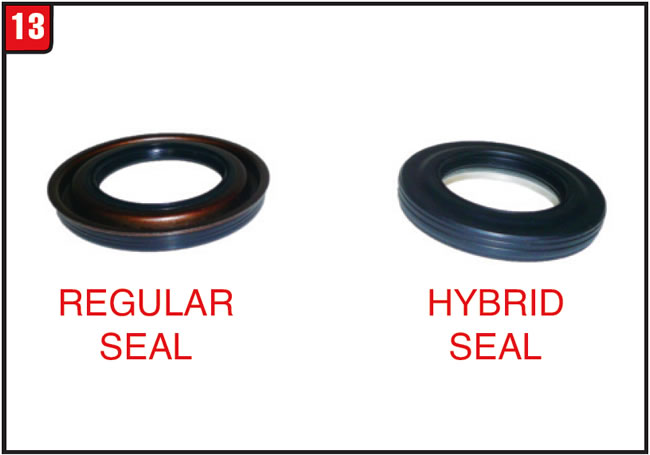
The regular seal on the left has a metal body with a flange whereas the hybrid seal on the right is rubberized without a flange. Beyond the basic design is the fact that for some reason GM wanted a Teflon-type of lip that rides on the torque converter hub. The two seals are definitely not interchangeable.
Normally, the difference would be no big deal; however, in this case it is a very big deal since the list price of the hybrid version is more than $130. The cost certainly puts this 6T40 metal-clad seal in the running for one of the most expensive seals ever made. When quoting a repair on this particular transmission, make sure to factor in the seal to avoid getting burned. The OE part number is 24246248. Who knows, maybe the aftermarket will come up with a less expensive alternative.


March 2017 Issue
Volume 34, No. 3
- Mercedes 7G-DCT FWD Dual-Clutch Transmission
- 6T40 / 6T50 Pump Metal Clad Seal Design


