

The original concept for the dual-clutch transmission occurred back in 1940, with the first unit production being launched in the early 1980s on a limited basis. It was not until 2003 that a modern mainstream DCT started to be produced in respectable numbers. BorgWarner and VW teamed up to produce a fairly advanced FWD wet DCT with all the bells and whistles including a mechatronic valve body. Since then, a variety of DCTʼs (wet and dry) have been developed to accommodate a wide range of vehicles and engine sizes.
The focus behind the DCT was to capture the best attributes of both automatic and manual transmission designs with the emphasis on manufacturing cost, drivability, durability and adaptability. The question became, what if a shift could be prestaged making the gear transition less abrupt, in effect, having two transmissions side by side working alternately. That is the basis of the DCT operation regardless of the frictional elements that the transmission is designed with.
In an effort to eliminate the third pedal (clutch pedal) in certain vehicles, manufacturers, beginning in the ʼ80s, started to automate regular manual transmissions (AMT). This new format was basically limited to high-performance applications. Automated or not, transmissions involved were basic manual-shift units with a traditional single-disc clutch assembly. Whether shifting and clutch operations were controlled by electrical components or not, overall function remained manual shift. Another approach was needed to improve performance. Enter the DCT.
A DCT has two input shafts, two output shafts (FWD) with normal gearing in between, all within a single housing. That arrangement requires a different engine/transmission connection than a traditional manual-shift clutch or automatic torque converter. The dual-clutch assembly (wet or dry) is the starting point of the transmission assembly. Regardless of design, this input (start) clutch in effect has two of everything with one set of components driving one input shaft and the other set of components driving the other input.
Controls also vary between wet and dry models as well as early and late model designs. Controls for one type of DCT could be strictly electro/mechanical while another type could be hydraulic with computer commands. The two main functions that require control are apply and release of the input (start) clutch, and the upshift and downshift of the transmission speeds.
Configurations do vary between FWD and RWD applications.
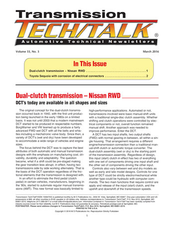
Today, there are a multitude of vehicle applications that come equipped with a wet or dry DCT, the bulk of which are FWD models. There are, however, a couple of RWD applications, one of which is in Figure 1. The DCT shown is from Nissan but, is not for a run-of-the-mill model. Nissan produces a high-performance racecar called the GTR, which cost in excess of $100,000 and is equipped with a 3.8L, 545 HP engine. In 2007, Nissan chose to use a wet 6-speed DCT for the transaxle assembly. The vehicle architecture is that of a Corvette, with both the transmission and differential mounted at the back with a driveshaft connecting the assembly to the engine. The driveshaft merely bolts to a connecting flange at the front of the transmission.
The Nissan GTR is some-what unique due to the fact that it is actually an AWD application, which is just a bit uncommon for a high-performance vehicle. For a racecar, the GTR is certainly on top of the heap when it comes to speed and, although limited in production, is gaining in popularity.
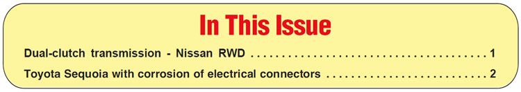
The name of the transaxle is the GR6 and like all other DCTs, it is fundamentally structured like a manual-shift transmission that has been automated. With the bottom pan and valve body removed, the internal view of the transmission would certainly mimic a stick (Figure 2). The cutouts in the forks could actually be controlled by a normal shift lever and rails like a standard shift, but that is not the case with the GR6. In addition to the regular sump filter, like any automatic transmission has, there is an auxiliary filter under the screw-on cap that should also be replaced during service.
Control of the GR6 is provided by a conventional, fully electronic valve body used in all late-model automatic transmissions, along with an additional feature. There are four hydraulically applied pistons that actually move the shift forks back and forth (Figure 3).
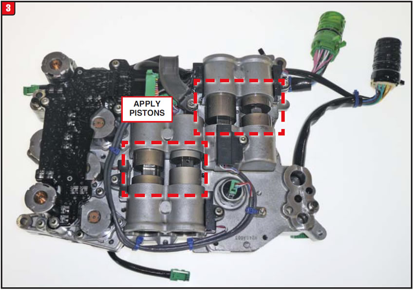
When commanded, the apply piston will move a given shift fork left or right to obtain the proper gear via the groove cut in the middle of the piston. With extended use, the area of the piston that contacts the groove in the shift fork can wear and create shifting issues. There are now metal clips available to correct that problem. At least the valve body is not a mechatronic design.
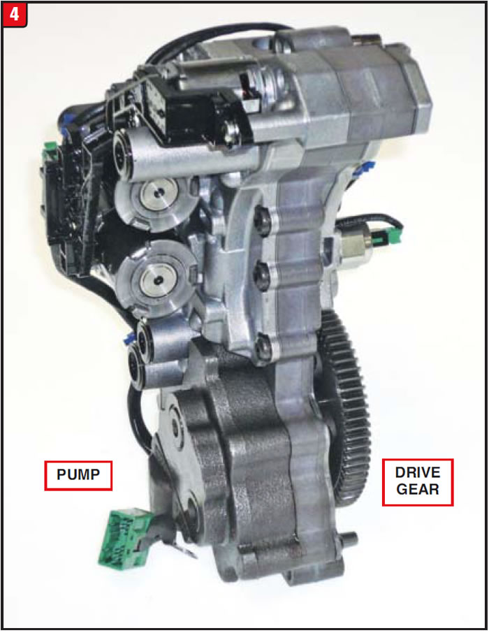
Unlike the valve body, the pump assembly is far from what would be in a regular automatic transmission. Aside from the shape of the housing looking more like a valve body than a pump, the assembly also has solenoids and switches like a valve body (Figure 4). The pump is driven by a fine-toothed gear that meshes with a drive gear mounted to the back of the dual-clutch assembly, which means a ratio is involved.
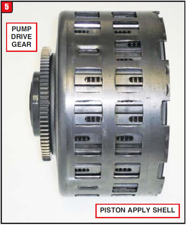
The item that enables a DCT to exist is the dual-clutch assembly, which is the starting point of both power flow paths, normally referred to as the odd and even gears. Whether wet or dry, the dual clutch assembly on a FWD application is normally connected directly to the engine. A RWD unit can be a bit different, as in the case of the GR6. The drive flange of the unit connects to a single input shaft that is splined to the dual-clutch assembly. All DCT clutch assemblies have differences, one to another, but the GR6 clutch assembly stands alone. What appears to be an outer shell is actually part of the apply piston (Figure 5). When the apply piston on the right end of the assembly moves, the outer shell actually applies the clutch pack on the left end. In addition, the drive flange on the left end of the unit contains the pump drive gear that rotates at engine speed.
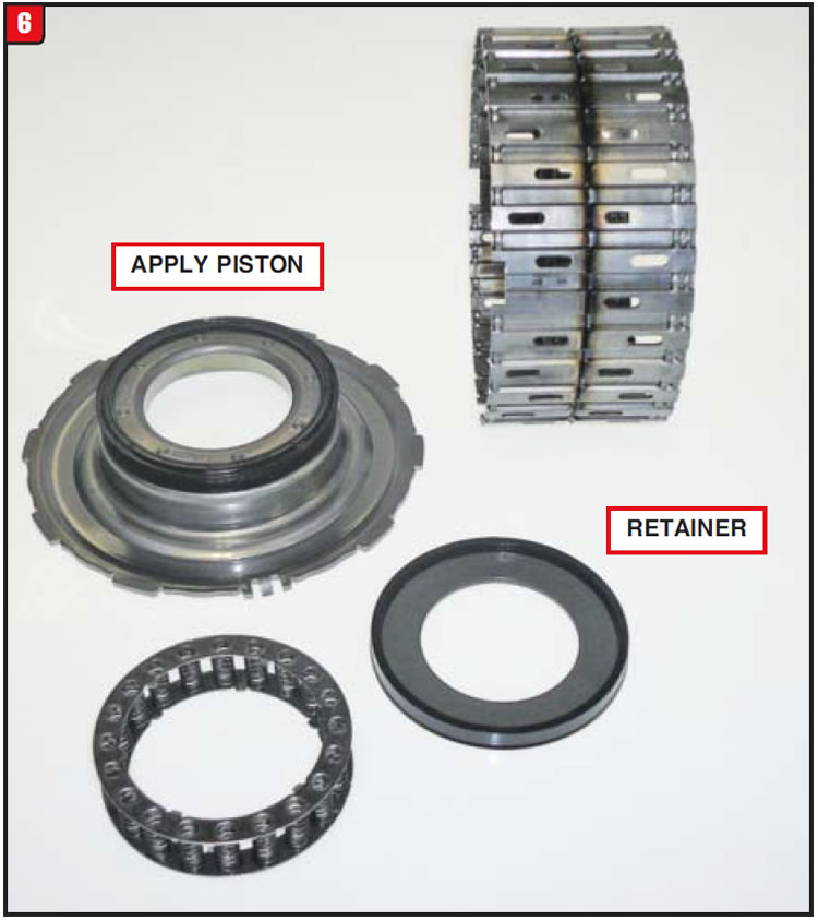
With the apply shell removed, the actual dual-clutch housing is exposed. The clutch housing is actually two housings welded together to form one assembly. The clutch housing contains two different clutch packs, one for each input shaft, as well as the related apply components. The apply piston that moves the outer shell is a bonded design and utilizes a bonded retainer and is the flatter of the two apply pistons (Figure 6). Although the piston is positioned toward the front of the transmission, the clutch pack that it applies is the rearward set that controls the hollow input shaft.
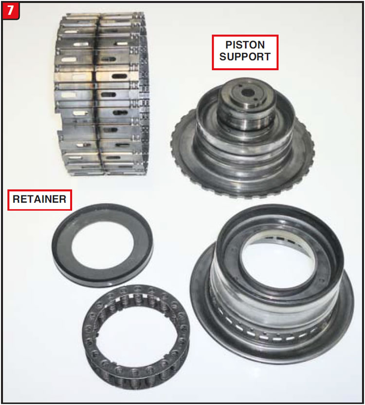
The other piston is somewhat different from the first, due to the design. This piston, which applies the clutches for the solid input shaft, is much deeper in design than the piston that connects to the apply shell (Figure 7). The apply piston inner support is deep because it is the bore for the sealing ring tower that bolts to the front case half. The return spring and bonded retainer for both apply pistons are, however, the same. Snap rings that hold the flanges to the clutch housing are different thicknesses, so verify the correct one before installing.
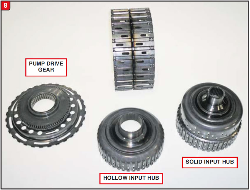
Although there is a noticeable difference between apply components, the frictions and steels of both clutch packs are the same, with the exception of a possible difference in thickness between steels, in order to obtain proper clutch clearances. There are two separate clutch hubs used within the dual-clutch assembly, with one hub partially riding inside of the other (Figure 8). The rearward facing hub splines to the larger hollow input shaft and is supported by a caged needle bearing which is pressed into the drive flange that contains the pump gear. The deeper dish forward hub has the smaller bore that splines to the smaller solid input shaft. There is no bushing or bearing between the two hubs; however, the clutch splines of the hubs are the same design. The pump-gear drive flange contains the notches for the tabs of the apply shell that contact the rearward friction pack.
The GR6 may be one husky transmission, but disassembly is not too brutal with a couple of exceptions of course. The differential assembly detaches easily from the transmission housing once the bolts are removed. After the pan and valve body are out of the way, the two transmission case halves can be split. The dual-clutch assembly and AWD unit are contained within the front case half along with the pump assembly. Before the dual-clutch assembly can be removed, there is a small snap ring that holds the assembly to the input shaft which must be removed first. Once done, the unit slides right out.
Before separating the main case housing from the intermediate plate, which supports all the gearing, there are a couple of snap rings as well as the AWD drive gear that must be removed. Those pieces are fairly obvious; what is not obvious is a support bolt that goes through the main housing into the reverse idler shaft, which must be removed or no cigar. With the shift forks removed, the main housing can be separated from the intermediate support plate.
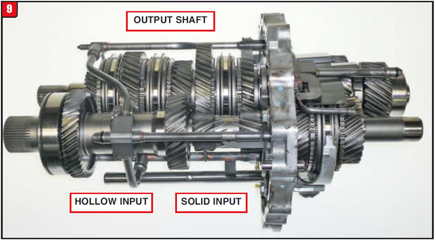
What is left at this point is the internal gearing, which looks suspiciously like any other manual-shift transmission (Figure 9). The item in a DCT that separates it from a manual shift is not obvious in the illustration, which is of course the dual input shaft set. A synchronizer can be mounted onto either input shaft or output shaft depending on design. The rest of the gearing remains fairly basic in comparison to other transmissions. Something that the GR6 does have, which other transmissions donʼt, is an inordinate amount of lube tubes to minimize wear or failure.
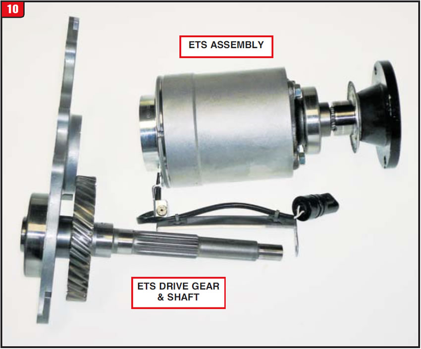
The remaining item that makes the GR6 unique is the all-wheel drive unit (ETS). The ETS is a fairly sophisticated design with how it operates. The unit contains a friction clutch pack that is applied by a magnetic clutch, which is why there is a harness attached (Figure 10). Internally, the clutch apply plate is like a swash plate with several ramps for steel balls to ride in and wedge between the electric motor. The problem is, if clutch clearance becomes excessive, the steel balls can fall out of position and create a bind-up of the unit. If this happens, the AWD drive gear shaft will break and thatʼs not good. The ETS unit contains its own special fluid.
Unlike other DCT applications that are either plentiful now or will be, the GR6 will remain a low-volume transmission; however, the price tag to do one will be substantial and there is actually product available currently, although not inexpensive.


The owner of a 2007 Toyota Sequoia had been having erratic transmission-related problems for several months, and after having another repair facility step up, unsuccessfully, decided to go for a second opinion. The vehicle was equipped with a 4.7L engine and an A750E five-speed automatic transmission with 83,000 miles on it. The unit was a 2WD as well.
Based upon symptoms and trouble codes, the other shop had apparently replaced a couple of solenoids and after each repair the vehicle worked well, at least for some time, but then things would go south. At some point it was recommended that the computer needed to be replaced, but at whose expense? The shop did not want to be liable for the cost of the computer replacement if it did not fix the problem.
When the car owner brought the vehicle in for inspection, he had a list of previous codes that were generated and also stated what the vehicle did from time to time. The codes and symptoms were not consistent month after month under various driving conditions, which is ultimately why the other shop wanted to replace the computer.
Initially, one of the trouble codes set was a P0973, which refers to a problem with the S1 solenoid. Another code that was set at the time was a P2714 that refers to an SLT (line pressure solenoid) issue. Previously, the codes were cleared and the transmission worked well, but then acted up again with erratic shifting and harsh engagement.
Later on, the owner would return with the vehicle doing something different. For instance, another trouble code would be set such as a P0974, which is also for a S1 solenoid issue as well as a P0977, which denotes a problem with the S2 solenoid. To make matters worse, transmission symptoms did not always coincide with the trouble code set. The question remained how to fix this thing without changing more widgets needlessly.

Although computers can and do go bad, they are probably not the first item on the list to replace. There is a lot of other stuff on a transmission or the vehicle itself that can create these types of issues. The first thing on the list was to check anything external that could be causing the erratic conditions that have plagued this vehicle. The wiring harnesses were checked for any breaks or loose wires as well as all of the grounds, but everything looked OK. Just as a precaution the pan was dropped to check for debris and the condition of the fluid; however, everything was clean and green.
Although the condition was getting progressively worse, the transmission worked well most of the time, which meant most likely it was nothing major, so it was decided to start probing specific computer signals. When the technician unplugged the external harness from the transmission case connector, everything became clear. Even though externally all the wiring seemed to be in great shape, the condition of the case-connector pins and the harness plug pin sockets was not quite as good. The connections were not rotting away from rust; however, several of the pins and sockets clearly had corrosion residue that was affecting electrical signals. Even the harness weather-pack seal seemed to be in pretty good shape. The condition of the pins would clearly be the cause of the erratic operation.

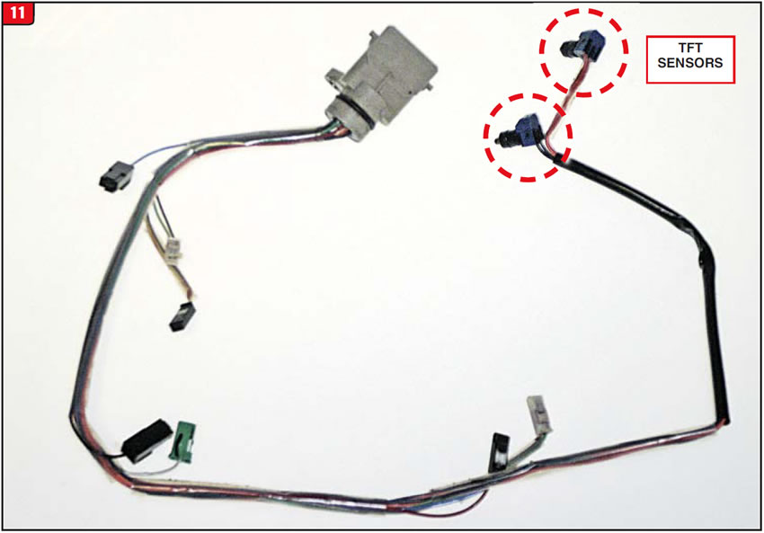
Corrosion of electrical connectors has been an increasing problem for years on a variety of vehicles, some more than others. Certain Toyota applications, however, seem to have an inordinate amount of connector-corrosion problems such as Toyota trucks. The case connector on an A750E is a molded design that includes the internal harness (Figure 11). Toyota RWD applications, five-speed or six-speed, all conform to the five-speed design with certain exceptions. For instance, the A750E has two temperature sensors instead of one like other transmissions have. The OE part number for the A750E is 82125-60650; however, always check for the correct part number based upon vehicle.
In addition to replacing the case connector with internal harness, it was decided to replace the external harness as well. To avoid replacing 6 feet of harness, Toyota provides a couple of repair packages. The external harness-connector plug is part number 90980-12293 and there is a wire terminal kit available under part number 82998-24250, which include individual terminals with wires.
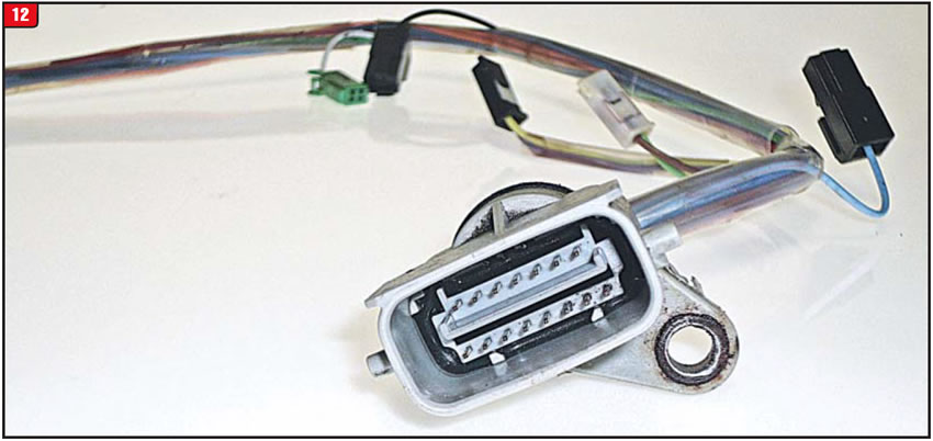
Whenever diagnosing a transmission that has multiple issues, always closely inspect the electrical-case connector (Figure 12). Corrosion or oxidation that can cause these issues may not necessarily be obvious but in fact can be somewhat subtle; therefore, always inspect terminals closely to avoid wasting time and money.


March 2016 Issue
Volume 33, No. 3
- Dual-clutch transmission – Nissan RWD
- Toyota Sequoia with corrosion of electrical connectors


