


A customer arrived at the shop with a 2009 Land Rover LR2 complaining of a noise. The vehicle was equipped with a 3.2L engine, TF81SC transmission and was an AWD. The vehicle was taken for a road test to determine the cause of the noise which was there for several weeks, according to the customer.
The noise was a growl coming from the back of the vehicle and was somewhat torque sensitive. The vehicle was put on a lift and, using a stethoscope, it was determined that the noise was coming from the differential.

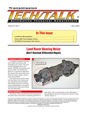
The noise, which sounded like it was coming from the pinion area, was more of a bearing growl than a gear whine. Due to construction of the differential, it was decided to pull the unit rather than repair it in the vehicle, (Figure 1).
The rear differential is produced by Ford in Sweden and is somewhat different than traditional differentials or final drives. There is a clutch pack assembly connecting the front drive flange to the drive pinion gear. Removing the front cover bolts will allow removal of the drum assembly and housing to gain access to the pinion gear. Once disassembled, the front pinion bearing was found to be bad, which apparently is a rather common failure.

Once the front cover and clutch drum assembly were out of the way, the end of the pinion was exposed. From this point things started to get a little ugly. The only part of the pinion shaft that was visible was the pinion spline because there is a metal-clad seal hiding the rest of the gear.
It may be necessary to drill a hole in the seal to attach a dent puller to remove the seal or whatever other trick can be utilized to pop it out. Once the seal is out of the way the pinion hold-down nut is accessible and must be removed. This is where things became a little more involved.
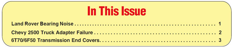
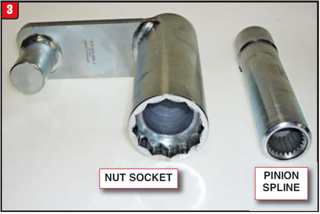
Land Rover recommends a specific procedure to disassemble and reassemble the pinion gear and requires a special tool to do it. The tool is part number JLR205984 and the cost is approximately $120, (Figure 2).
The outer sleeve meshes with the 12-point locknut and the inner sleeve splines to the pinion shaft itself. Unlike other arrangements, it is the pinion shaft that gets rotated while the nut is held stationary by the tool outer sleeve, (Figure 3).
Although a thread sealer was applied by the OE, it is not advisable to heat the nut or use an impact gun as damage to the pinion threads can occur. The differential should be anchored to a bench and the tool outer sleeve also must be held stationary. The nut is a right-handed thread, so make sure that the pinion shaft is rotated in the correct direction to remove the nut.
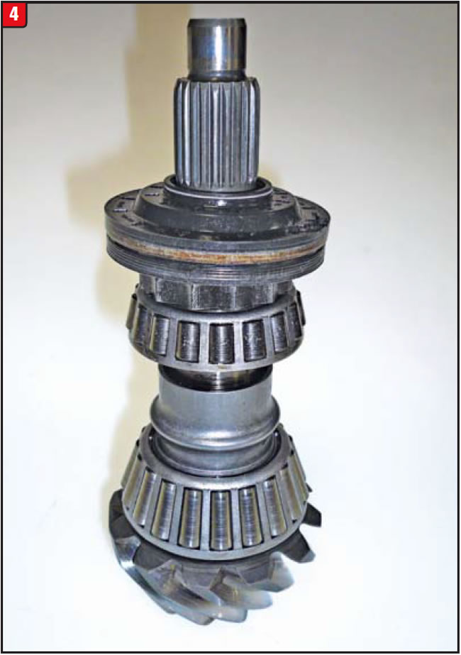
With the differential side cover and ring gear/carrier out of the way, the pinion gear can be pressed inward to expose the front bearing and race. The front bearing is smaller than the rear and uses a crush sleeve in between, (Figure 4). Note: the front bearing in the photo is flipped from its normal position in order to show the wear. The layout is correct however.
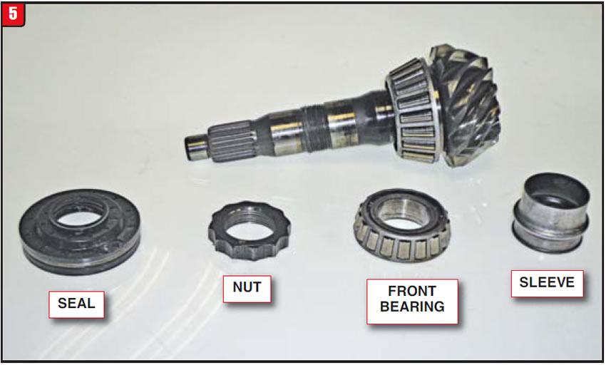
Normally, the pinion rear bearing is not damaged, but should be closely inspected nonetheless. Individual components are available from Land Rover and are not too costly. The pinion gear component numbers are as follows:
- Metal-Clad Seal………LR023442
- Nut…………….…………LR050541
- Front Bearing………..LR023441
- Crush Sleeve…………LR023443
The items are shown in Figure 5.
When assembling the pinion gear, ensure that everything is clean to obtain proper bearing preload. Using the tool, turn the pinion shaft to tighten the assembly in increments, making sure that the bearings are free. Ultimately, the torque on the nut/shaft is 147 ft. lbs. Use caution when installing the double lip metal-clad seal which separates the two oil reservoirs within the differential.
After reinstalling the ring gear/carrier and side cover, the front cover and drum assembly can be installed. The Land Rover LR2 uses a differential that senses torque requirements under all conditions. The unit is called Active On-demand Coupling (AODC) and is a somewhat involved torque-sensing system.
The AODC is linked with all onboard modules and can respond quickly. The coupler connects the driveshaft to the pinion gear with varying amounts of slippage.
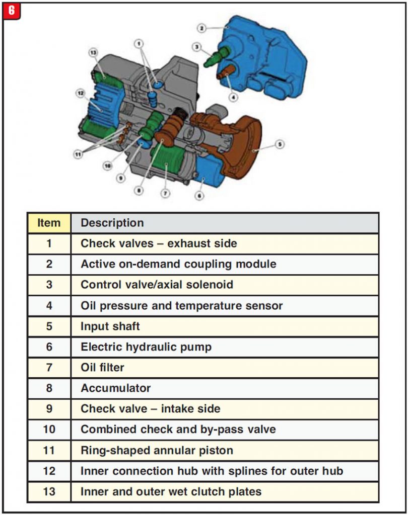
The AODC consists of several components ranging from an electronic module to sensors and solenoids, valves, electric/hydraulic pump and clutch-pack assembly, (Figure 6). Currently the coupler assembly is not repairable due to parts availability.
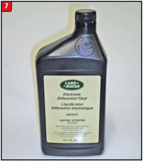
After repairs are made, the differential must be refilled, but again (unlike other models) there are two different oils, not one. The oil that goes into the ring and pinion cavity is a normal grade of differential oil, whereas the AODC uses a special fluid due to electrical/hydraulic components, (Figure 7). The part number is LR019727 and is quite expensive, so donʼt spill any.
Addressing the noise issue is a decent repair job, dealing with AODC operation issues will be an entirely different matter.


A customer with a 2003 Chevy 2500 truck arrived at the shop with a couple of issues. Apparently, the truck had what started out as a minor vibration, but became a major vibration due to neglect of the customer who must subscribe to the old adage “Drive it ʻtil it stops”.
As if the vibration wasnʼt enough, the customer started to notice oil spots under the truck. Itʼs unclear as to when lightning struck and the customer realized that these increasing events were probably not a good thing, but he did at least bring in the vehicle for inspection.
Although the truck had 140,000 miles on it, the overall condition was not too bad and the engine ran quite well. During the road test, the vibration, which was torque sensitive, did not rattle the dashboard out of the vehicle, but almost. It was a short road test.
After the road test, the truck was put on a lift to see what was falling apart. It required little diagnostic expertise to see that the driveshaft front U-joint was a heartbeat away from coming apart. Talk about luck!Now, what about the leak?
The truck, which is a 4WD, was wet at the back of the transmission (a 4L80E) and in front of the transfer case. Although initially the cause of the leak was not very obvious, it became really apparent once the transfer case was moved back, (Figure 8).
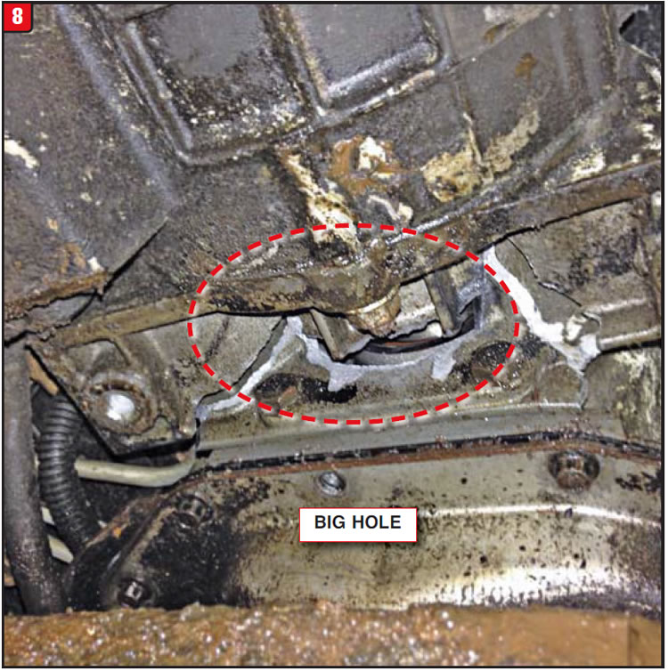
The excessive driveshaft vibration caused an over-load on the entire powertrain and the weakest link of the chain took the hit, which was the transmission-to-transfer-case adapter housing. Driveline vibrations can inflict damage on a variety of components from bushings and bearings to mounts.
Not only did the offending U-joint get replaced, but upon closer inspection, two other joints needed replaced as well. Because the customer was oblivious to the initial problem, repairs extended beyond the universal joints.
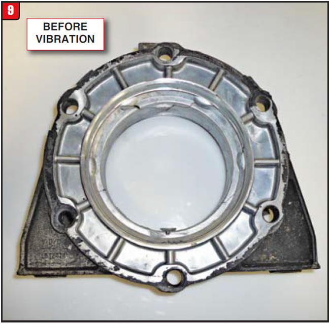
The transfer case was removed in order to change the adapter housing. Normally the adapter housing is a one-piece unit, (Figure 9).
With a little help from worn-out joints, that one-piece adapter can become a two-piece adapter, (Figure 10).
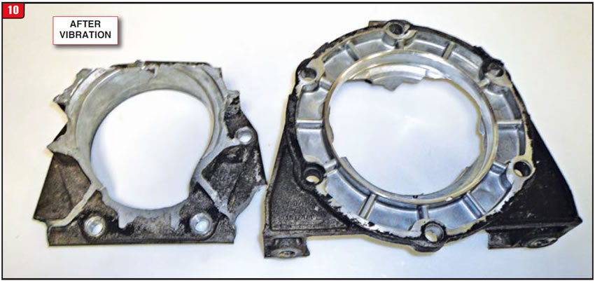
The part number for this particular adapter is 15724745 and is a pretty good mover. Whether due to corrosion or fatigue, these adapter housings do tend to fail, so always inspect them closely. When doing a routine service on any vehicle it is always a good practice to inspect all driveline components; however, when it comes to trucks (and especially work trucks) it is doubly important. Not doing so can turn a minor repair into a major fiasco.


The cost to develop a transmission from scratch has been astronomical over the past couple of decades for a variety of reasons. Back in early 2000, GM and Ford were hit by a stroke of brilliance and decided to put away their swords for a time and jointly develop a new level of transmission. Although both car companies followed the ZF lead for a rear-wheel-drive six-speed, when it came to a new front-wheel-drive six-speed they started with a clean sheet of paper.
After putting their engineering heads together, the GM 6T70/75 and Ford 6F50/55 transmissions were born. From the start, much of the two versions were the same, beyond the basic architecture. Although many of the components were the same, others differentiated for specific calibration reasons. Like all transmissions, the 6T70 and 6F50 models also have had upgrades to certain items for drivability and durability reasons.
One such component that started out being common between GM and Ford, but has changed a bit was the transmissionʼs end cover (Figure 11). The end cover gasket is metal with a bonded rubber rib around it and is common to both models of units. The end cover contains two stationary brake-apply pistons – the 2-6 and low-reverse, which are both held in by snap rings.
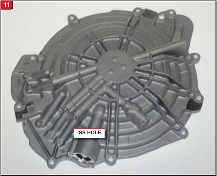
The low-reverse piston is the larger of the two and both pistons are common to GM and Ford. The covers also have a sealing ring support that bolts to the cover, but is not available separately. The support sealing rings are for the 3-5/reverse and 4-5-6 clutch assemblies. Finally, the ISS (input speed sensor) is located in the case cover. The ISS is bolted in and the sensor probe extends through the cover to pick up the reluctor which is attached to the input shaft. Although the ISS wiring is different between GM and Ford (GM has two pins and Ford has three), the length and diameter of both sensors are the same. There is approximately a 1/8” air gap between the sensor probe and reluctorʼs outside diameter.
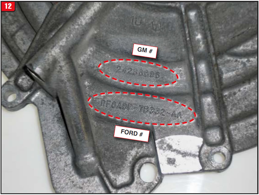
The first covers that went into production came from one supplier and were certainly common. Both the GM and Ford part numbers were cast right into the cover (Figure 12). The GM cast number was 24236696 and the Ford number was 8A8P-7B332-AA. Even though there was one cover with both manufacturersʼ numbers on it, buying a new one at the dealer would require the respective OE service numbers.
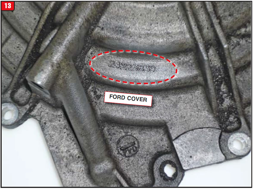
Another variable back then was number inconsistency. For instance, occasionally you would take a cover off of a Ford 6F50 and find only a GM production number cast into it (Figure 13). That number was a GM 24223839. There was little difference between the freak cover and dual number cover.
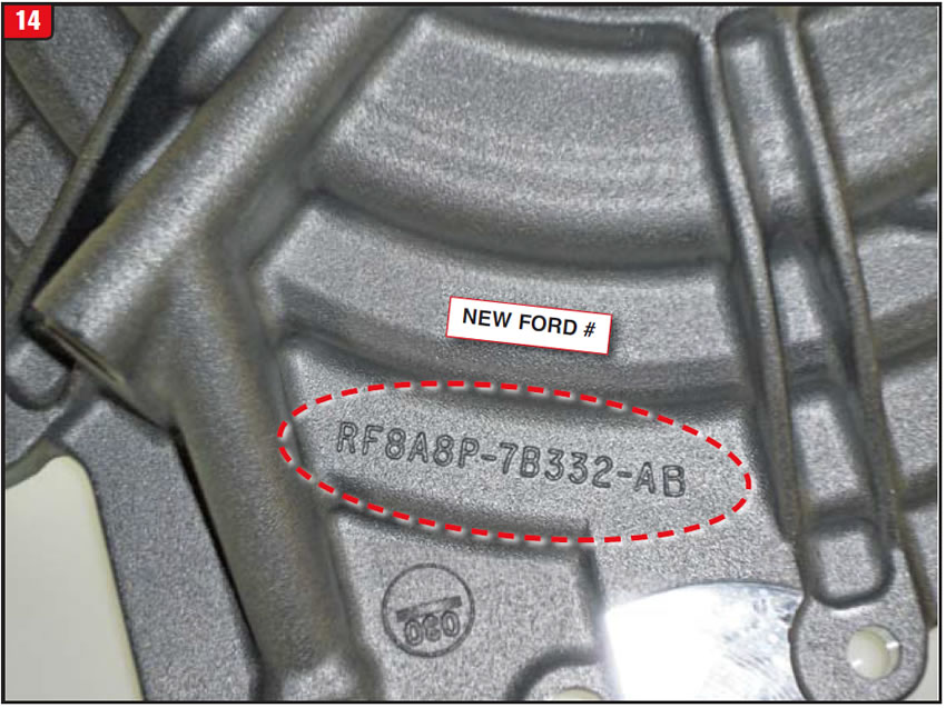
Recently, the winds of change have accelerated concerning the end covers at GM and Ford. At Ford, a new number was released, but with little physical difference. The service part number is 8A8Z-7222B with a casting number of 8A8P-7B332-AB (Figure 14).
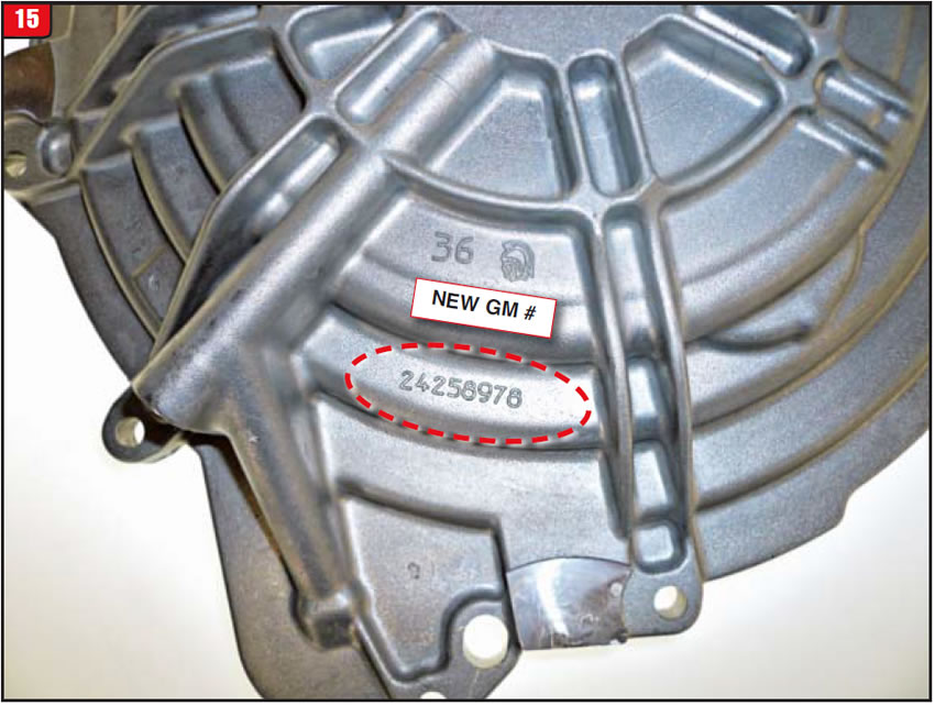
At GM, a couple of additional wrinkles have popped up. Beginning in 2012, the 6T70 entered into a new phase called Gen II. Several components have changed for Gen II including the end cover. One minor change had to do with the compensator spring that is installed into the cover. The new spring is red in color. Beyond the spring, a slight change was made to the sealing-ring support bolts, but not much else. The new GM service number is 24260590 with a casting number of 24258978 (Figure 15).
Currently there is another issue at GM concerning the 6T70 end covers. They are on restriction using a “car down” scenario. A VIN is required to obtain a new cover from a dealer. This may be caused by a supply issue due to the minor changes to the cover or a change in supplier. Normally, an end cover does not need to be replaced due to failure of the cover, but rather something else like the 3-5/reverse waved-spring breaking. The sealing ring support also is starting to wear, requiring replacement, but not enough to warrant restrictions.
If a GM cover is unavailable, the logical choice would be to buy the Ford cover; however be prepared, because the cost of the Ford version is approximately$100 more than GM. The reasons why things change, sometimes are not too visible.

March 2015 Issue
Volume 32, No. 3
- Land Rover Bearing Noise
- Chevy 2500 Truck Adapter Failure
- 6T70/6F50 Transmission End Covers


