

Issue Summary:
- We provide exploded views of the valve body and identification of components in AW50-42LE units.
- After overhaul, the speedometer on a Volvo/SAAB vehicle equipped with a 50-40 LE series transaxle may register in the Park position, and there may be no Reverse when the driver selects Reverse from the Park position.

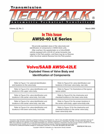
- Refer to Figure 1 for solenoid identification and locations on the valve body.
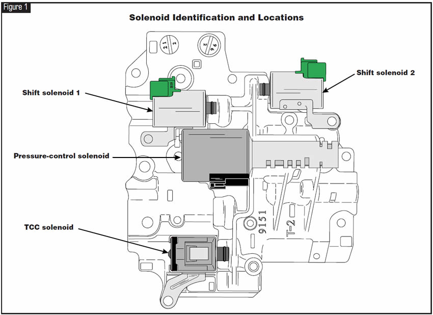
- Refer to Figure 2 for valve identification and locations in the upper valve body.
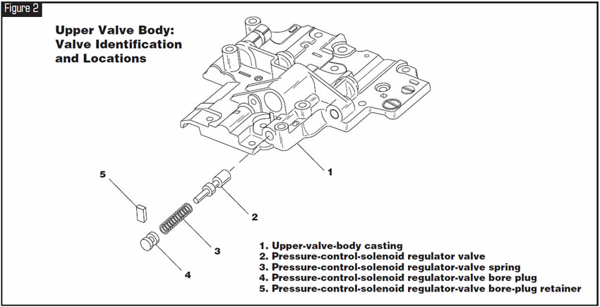
- Refer to Figure 3 for valve identification and locations in the center valve body, front side.
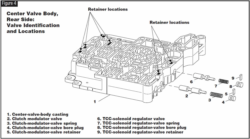
- Refer to Figure 4 for valve identification and locations in the center valve body, rear side.
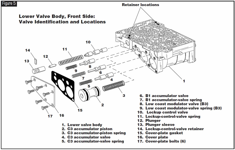
- Refer to Figure 5 for valve identification and locations in the lower valve body, front side.
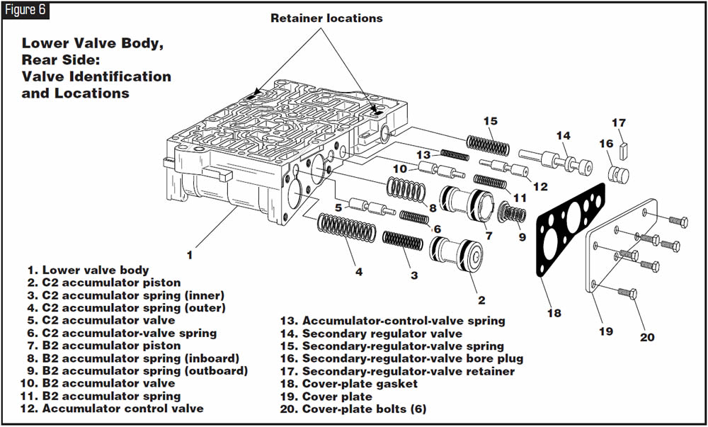
- Refer to Figure 6 for valve identification and locations in the lower valve body, rear side.
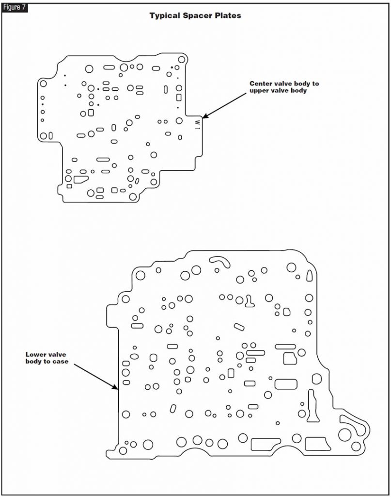
- Refer to Figure 7 for illustrations of the typical spacer plates.
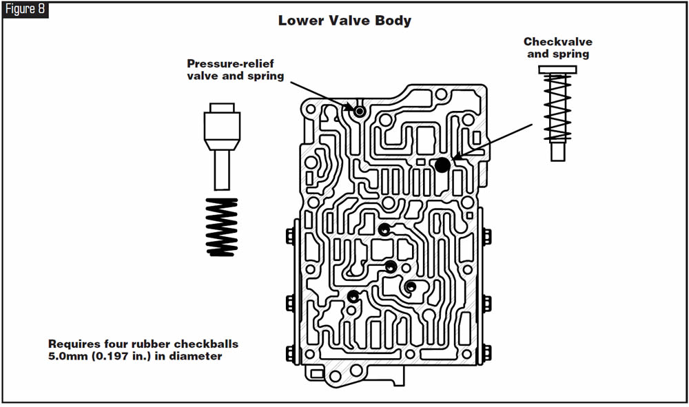
- Refer to Figure 8 for the checkvalve and checkball locations in the lower valve body.
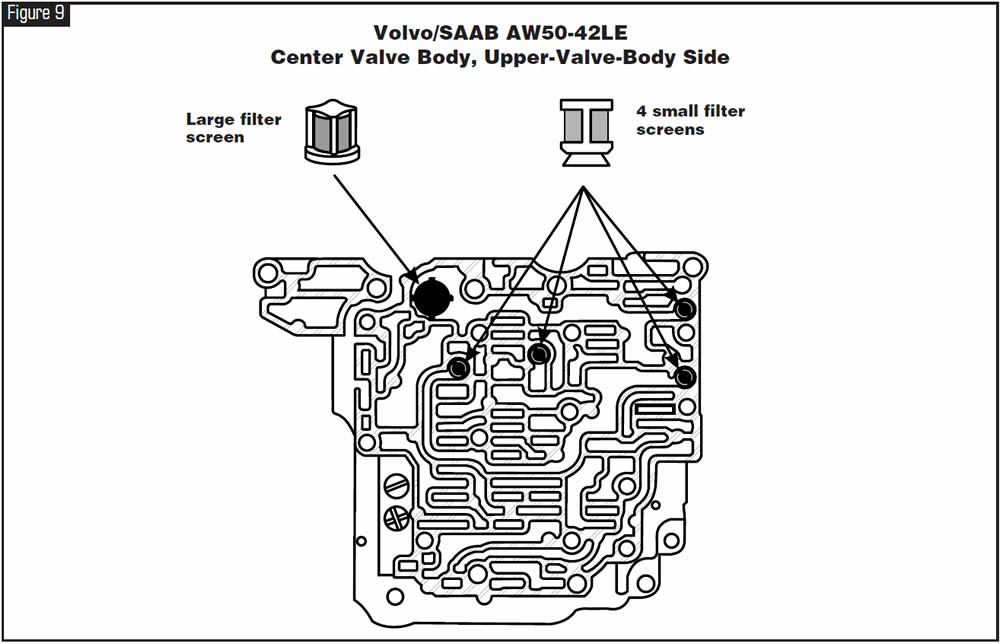
- Refer to Figure 9 for the screen locations in the center valve body, upper-valve-body side.
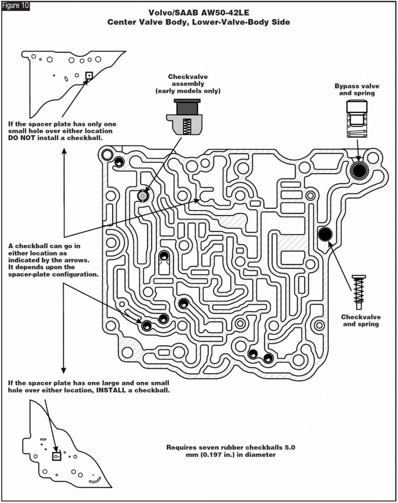
- Refer to Figure 10 for the checkvalve and checkball locations in the center valve body, lower-valve-body side.


After overhaul, vehicles equipped with the 50-40 LE series transaxles may exhibit a speedometer that is registering in the Park position and no Reverse when the driver selects Reverse from the Park position. Reverse will engage if Drive is selected before Reverse.

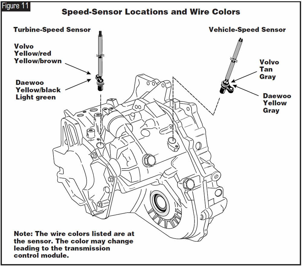
The cause may be that during installation, the vehicle-speed sensor was placed into the location of the turbine-shaft-speed sensor on the case. This will create a vehicle-speed reading in the Park position because of the turbine shaft’s rotation in the Park position. The transmission control module will cancel Reverse application by turning on solenoid 1 to block the application of the B3 clutch, which is the low/reverse clutch. Once the selector is placed into Drive, the turbine shaft will come to a stop and Reverse will apply from the Drive position.

Refer to Figure 11 for the wire colors of the turbine-shaft-speed sensor and the vehicle-speed sensor and their correct locations on the case.

March 2005 Issue
Volume 22, No. 3
- Volvo/SAAB AW50-42LE: Exploded Views of Valve Body and Identification of Components
- Daewoo/Volvo AW50-40 LE Series: No Reverse


