
TASC Force Tips
- Author: Gregg Nader, Sonnax
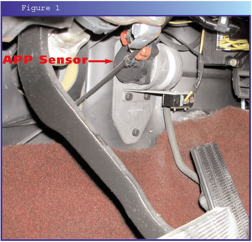
In 1994, GM introduced its electronic diesel fuel-injection pump to the 6.5-liter engines. This “drive-by-wire” system has no throttle cable, instead using an accelerator-pedal-position (APP) sensor. The APP sensor is the main input for determining how much fuel the engine should receive, and also how much line pressure the transmission should have. This system is easily identified, because the APP sensor is attached directly to the throttle-pedal bracket (see Figure 1), and there is no throttle cable.
1994-98 injection pumps have a history of drivability problems, including hesitation, hard or no starts, and poor performance or fuel economy. Because of this, GM has extended the warranty coverage from five years/100,000 miles to 11 years/120,000 miles with a special policy warranty (see GM bulletin #00064A). The original 1994 95 models are the most susceptible to wear, and newer models are manufactured with more-durable materials. However, problems can occur on any 1994 or newer electronically controlled injection pump.
When working on a 1994 or newer diesel-powered truck with a 4L80 E transmission that has soft, sliding shifts; poor line rise; and burned forward, intermediate and direct clutches, be sure to include the diesel injection pump in your checks as a possible cause for the transmission problem. One of the problems with this injection pump is an internal leak that prevents the computer from having full control, and allows the engine to receive more fuel than the computer requested.
The computer controls the relationship between transmission line pressure and engine power, and it knows exactly what the amperage of the transmission pressure-control solenoid (PCS) should be at any given throttle position and engine speed. During normal operation, the throttle is pushed down 50% to 100% when the vehicle is pulling away from a stop. However, a truck getting extra fuel from a bad injection pump will accelerate from a stop using only 2%-10% throttle! With this situation the computer will not command enough EPC/line-pressure increase to prevent transmission slippage. The result is soft, sliding shifts and burned clutches. Leaking injection pump = more fuel to burn = less throttle used to accelerate = less commanded line pressure = clutch slippage.
The fuel solenoid on the injection pump controls fuel delivery to the injectors. The “extra”-fuel problem occurs when the internal parts of the injection pump wear or become scored and allow fuel to bypass the electronic controls. The wear/scoring in the injection pump is caused by contaminants in the fuel as a result of a failed fuel lift pump, bad fuel or the injection pump itself. Once damaged, the injection pump must be rebuilt or replaced. Flushing the fuel lines and tank and disposing of any remaining fuel also are recommended.
The easiest way to diagnose this problem is with the engine hot and the transmission in Park or Neutral. Slowly increase engine speed, and try to hold the engine at 2,000 rpm. When the injection pump is working normally, this will not be a problem, but if the speed continues to increase while you hold the throttle steady, then suspect a bad pump. That’s right; the truck can start and idle fine and seem to drive OK, too, with the only symptom being uncontrollable engine speed in Park or Neutral.
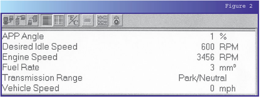
To confirm this, first remove the plenum runner between the turbocharger and the intake manifold. Remove the crankcase ventilation tube that runs between the valve cover and the air-cleaner duct. With the engine running, use a scan tool to monitor the fuel rate. Normal fuel rate is 10-13mm at idle, and fuel rate should increase as engine speed goes up. Now try to hold engine speed steady at 2,000 rpm while watching the fuel rate. If engine speed increases and fuel rate goes down, this shows the computer is trying to control engine speed by decreasing the fuel rate to the injectors (Figure 2 shows 3,456 rpm at 1% throttle opening!). When this happens, you’re most likely dealing with a bad injection pump. Even though the computer is cutting back on fuel, the engine speed increases because of the worn injection pump. Also check the fuel rate at idle, and if it’s below 6mm, this is another indicator that the engine is getting extra fuel and the computer is lowering the commanded fuel rate to maintain the correct engine speed.
Any oil that gets into the air-intake tract will be burned and will contribute to “extra fuel” for a diesel engine. Inspect the runner and intake plenum for oil residue. Some oil film is normal, but there should be no puddles of oil. To check for leaking turbocharger oil seals, place a piece of cardboard near the turbocharger outlet. With the engine running, increase engine speed until the turbocharger spools up, and if the turbocharger sprays an oil mist onto the cardboard, the turbocharger oil seals are leaking and must be replaced.
Special thanks to George Krikau at Huckstorf Diesel in Franklin, WI, for contributing to this article.
The TASC Force (Technical Automotive Specialties Committee) is a group of recognized industry technical specialists, transmission rebuilders and Sonnax Industries Inc. technicians.


