
TASC Force Tips
- Author: Gregg Nader, Sonnax Technical Center
The last thing I want to do is put you to sleep with an article on performing electrical tests and Ohm’s Law. What I want to show here is something that I think is really exciting: load-testing solenoid circuits with an ammeter! Using an ammeter and a calculator can save time, LOTS OF TIME. How would you like to check the power distribution, ignition switch, external and internal wiring, solenoids, computer and computer grounds without putting the vehicle on a lift or even raising the hood?
- The ampere (amp) is the unit that indicates the rate of electric current flow.
- The ohm (Ω) is the unit that indicates resistance to current flow.
- The volt (V) is the unit that indicates electrical potential.
We have all been taught to test circuits by measuring circuit resistance with an ohmmeter. Although this works well in many instances, there will always be circuits that check OK by resistance but will fail when a load is applied. Load-testing stresses the whole circuit the same way it works during normal operation and is the fastest and most-effective way to diagnose electrical-circuit problems.
The way I like to remember Ohm’s Law when in the shop is with the acronym VCR, same as the now-outdated videocassette recorder, only here it refers to V= voltage, C= current, R= resistance.
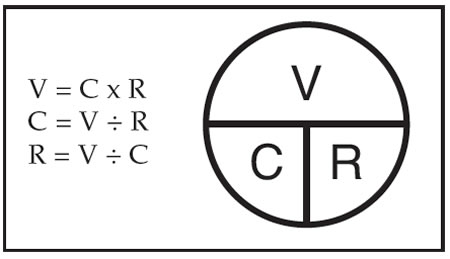
If you know the amperage a solenoid draws and the circuit voltage, then circuit resistance is easy to find by applying Ohm’s Law.
Testing current flow through a circuit can be done at the beginning, middle or end of the circuit, since the amperage is the same in all parts of the circuit. Here are three approaches to load-testing circuits and performing amperage tests that can make life in a transmission shop easier.
If you have a GM vehicle with solenoid or quad-driver codes, or you need to verify system integrity, try this method:
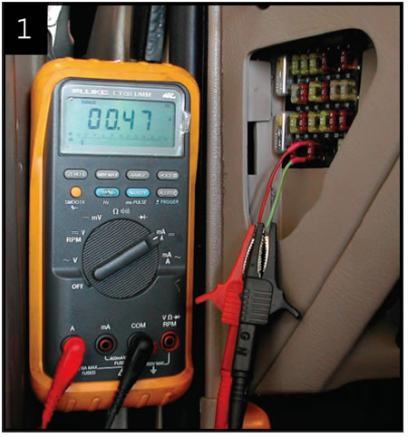
Remove the transmission fuse. Put the leads of your ammeter in place of the fuse that was removed (see Photo 1). You can connect your meter leads to the fuse receptacle with the blades from an old fuse. Now any current (amps) that feeds the transmission will go through the ammeter. If the shift indicator or some other device is drawing current from that fuse location, then zero out your ammeter before proceeding.
Use a scan tool with bi-directional controls to command the individual solenoids on (see Photo 2) and measure individual solenoid current draw. Generally a 24-ohm solenoid will draw about 1⁄2 amp. A 12-ohm solenoid will draw about 1 amp. To determine your exact circuit resistance, check your exact voltage and apply Ohm’s law.
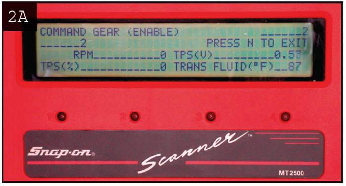
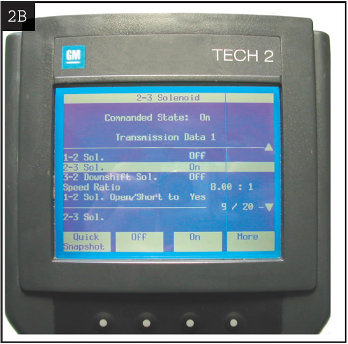
Example 1
13.88 volts divided by 1.13 amps equals 12.2 ohms circuit resistance.
Testing this way checks everything – power supply, ignition switch, alarm relays, wiring, solenoids, computer and grounds. This will quickly verify good circuits and isolate bad ones. Not bad for five minutes’ work with a scan tool, ammeter and calculator.
Bi-directional scan-tool controls apply to only some vehicles. If your scan tool cannot control individual solenoids, a more-universal method to load-test circuits is to use your ammeter to energize solenoid circuits directly by supplying power or ground as needed.
Use a schematic to identify wire color and terminal location and to determine whether the computer supplies power or ground to the solenoids. You can perform the job of the computer and turn the solenoids on and off with your ammeter. Remove the connector from the computer and supply power or ground through your ammeter to the individual solenoid wires at the computer connector (see Photo 3). Although this does not check the computer or its grounds directly, it is a versatile way to load-test the solenoids and wiring. Again apply Ohm’s law to determine exact circuit resistance and compare this with the solenoid resistance specifications.
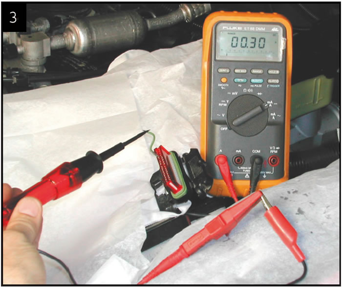
When load-testing this way you must be careful when energizing low-resistance solenoids such as PWM, EPC or fuel injectors. Resistance in these solenoids is as little as 2 ohms Connecting 12 volts directly to a low-resistance solenoid can draw enough current to cause circuit or component damage.
Example 2
12-volt circuit with a 2-ohm solenoid will draw 6 amps of current
Six amps is enough to power the headlights and could damage the wiring and supply circuits.
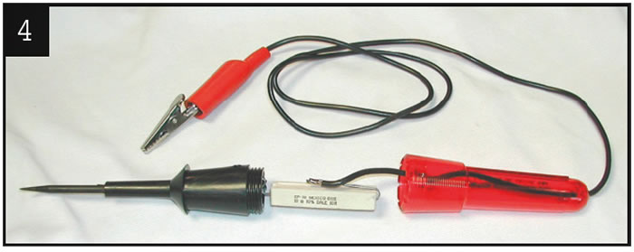
A safe way to load-test low-resistance circuits is to limit the amount of current during the load test by adding extra resistance. Photo 4 shows a test light that has been modified by replacing the bulb with a common 10-ohm by 10-watt resistor. This tool is available from Schaffer Test Products. The added resistor will limit current flow and prevent circuit damage during testing. Use this as a test-lead extension between your ammeter and the circuit you are energizing. Measure current draw through the circuit and the resistor probe. Apply Ohm’s law to get the total resistance value (including the probe), and then subtract 10 ohms to get your final circuit resistance value. Adding 10 ohms from the probe to the 2-ohm solenoid equals 12 ohms. A 12-volt circuit with 12 ohms resistance will allow only 1 amp of current draw. Now instead of drawing 6 amps, the same circuit draws only 1 amp!
Example 3
13.88 volts divided by 0.625 amp equals 22.2 ohms, minus 10 ohms (from the resistor probe) equals 12.2 ohms circuit resistance
Example 3 is the same as example 1, but the load-testing was done with a fraction of the current draw. This procedure works very well for testing low-resistance EPC and PWM solenoids or fuel injectors, or just for an added measure of protection.
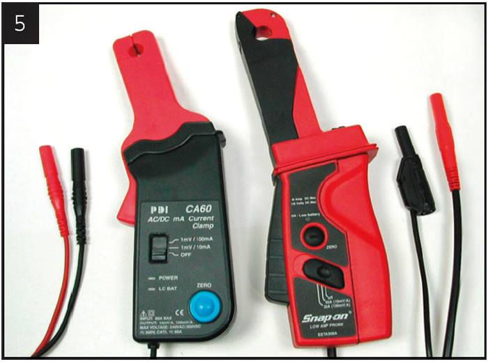
You also can check amperage by using a clamp-on inductive sensor or low-current probe (see Photo 5). This type of tester has recently become more common. These low-current probes have a range from 40 amps down to just a few milliamps. The nice thing about these testers is that you do not have to disrupt the circuit that you want to check – no unplugging, cutting or splicing. When connected to a voltmeter, the amperage probes give a readout on the DC voltage scale that directly relates the current in the clamped wire. The voltmeter reading is in volts/millivolts, not amps. All that is necessary to convert the voltage reading to amperage is to move the decimal point to the right.
With a clamp-on sensor you can perform the same type of tests already described. Or you can place the clamp-on sensor onto individual solenoid wires, then operate the vehicle on a lift until that solenoid is energized while you’re measuring current flow. Load-testing with this procedure will work best on on-off type solenoids. The variable-duty-cycle control of PWM and EPC solenoids also can be monitored, but it will be difficult to apply Ohm’s law and calculate circuit resistance unless the solenoid is turned on 100%.
Understanding and using Ohm’s law is one of the basic necessities when working with electrical systems. Try these diagnostic tips next time you have trouble with an electrical problem and see how much time you can save.
Thanks to Bob Goodman of Jasper Engines & Transmissions for his suggestions and input.

The TASC Force (Technical Automotive Specialties Committee) is a group of recognized industry technical specialists, transmission rebuilders and Sonnax Industries Inc. technicians.


