TASC Force Tips
- Author: Devin Gallagher
- Subject Matter: Undeclared problems are your problems
- Action: Inspect driveline first
In the transmission business, overlooked driveline problems are a cause of comebacks that are not related to your build but can still hurt a shop’s reputation. Making some basic checks of the vehicle while it’s still in the shop can get ahead of many driveline-related issues and help reduce comebacks.
Picture this: the 4L60-E you just built is ready to come off the bench for installation back into a Chevy pickup, or perhaps it was a 4R70W in a customer’s F-150 – either way the story is the same. Overall, it was a quick diagnosis and a standard rebuild. The R&R man stabs the transmission back into the vehicle and eases the slip yoke through the new seal and bushing, back onto the output shaft. After bolting the flange yoke up to the rear end and a test drive to ensure everything is working properly, it is delivered to the smiling customer, who drives away.
But, during the months before your rebuild, the customer did not notice the developing noise and slight vibration caused by a failing U-joint. On the initial test drive, it did not grab your attention either, though the joint would have failed a visual inspection. A few weeks after the build, your customer is back in the shop describing the terrible vibration and the puddle of transmission fluid in his driveway, and how it definitely was not that way before you worked on it.
After a quick inspection, it is determined the U-joint failure created excess play and vibration that damaged the new seal and bushing, resulting in a leak. But as you try to explain what caused this issue, it becomes apparent that the customer thinks he is being taken advantage of. The bottom line to the customer is that it must be your fault, even though that is not the case. Though you have done nothing to deserve it, trust is quickly eroding.
It is easy to focus solely on diagnosing and fixing a customer’s stated problems, since you are already so busy and most customers tend to resist up-sells. But the situation above shows why we must combat the temptation to focus only on customer concerns. If the U-joint had been inspected before rebuild, its failure could have been brought to the customer’s attention. If the customer had declined the repair, your backside would have been covered when the part failed completely. For this reason, it is wise to inspect each vehicle that comes through the shop for any problems that could begin or worsen through your warranty period.
Remember, you do not enjoy advantages like a doctor who gets to charge each time a patient comes in with a seemingly related issue; you are expected to hunt down and eradicate all problems the first visit, whether they are related or not – an unfair, but an unfortunate double standard that we have learned to live with as technicians.

Fortunately, there are simple visual and hands-on inspections that can be performed on each driveline to ensure you don’t get derailed by a confused and angry customer.
Driveshaft noises and vibrations are most commonly caused by:
- Improper balance
- Worn U-joints
- Extreme runout or out-of-phase driveshaft
- Worn extension housing bushing
- Excess slip yoke play
- Compromised carrier bearing
- Failed pinion bearing
Some of these issues can be detected and addressed at your shop without the need of a professional driveshaft builder. For the thornier issues, a good working relationship with a knowledgeable driveshaft shop can prove just as important as knowing how to identify and repair driveline issues in-house. Advantages to working with a driveline professional include:
- Assistance in pinpointing driveline noises
- Expert help detecting vibration or angle issues
- Building a new driveshaft
- Re-yoking a shaft
- Assistance with straightening or balancing a shaft
As a bonus, driveshaft builders often need assistance with transmission problems, and developing a relationship with one of these folks can help you reap lucrative referrals.
The following overview will help you consistently check RWD driveline components for signs of damage and wear. If any of these items are unfamiliar, your chosen driveline shop should be happy to give you any guidance you need.
Driveshaft tube & weld yokes
The O.D. of the driveshaft should be inspected for straightness and noticeable nicks or dings. A driveshaft tube with significant dents or scarring is more prone to failure at these locations. If you suspect a bent shaft, sometimes a dial indicator can be used on the O.D. to verify runout. However, in Rust-Belt areas this can be difficult due to scaling (on steel) or pitting (on aluminum) driveshafts.
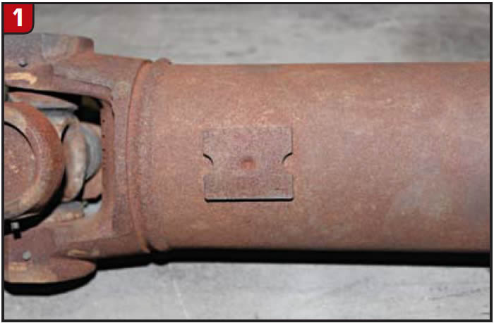
Check the integrity of the welds for cracks. Check to see if any of the weights used in original balancing are missing – they should be present near the ends of each driveshaft tube segment (Figure 1). When a weight is thrown off, there often is a telltale witness mark left behind to betray it.
When you do suspect an issue, a driveline shop can help determine if a tube can be rebuilt using the original weld yokes or if a new driveshaft is required.
Slip yoke
The slip yoke must not be bottomed out or fully engaged up to the yoke ears when installed. If the slip yoke is prevented from sliding through its full range in response to suspension travel, broken parts, noises and other trouble will follow. In general, a slip yoke is properly seated on the output shaft with roughly 0.75 inches to 1 inch from the bottom of the ears to the end of the extension housing seal.
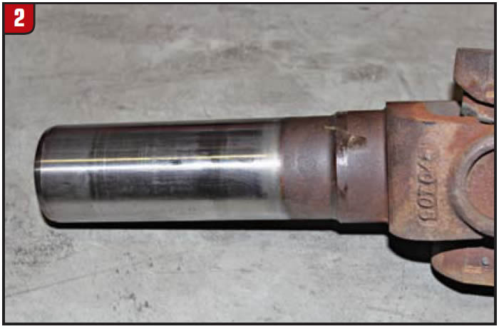
Check spline fitment for excessive play and ensure the slip yoke slides in and out of the transmission smoothly. Spline engagement must not be too tight or loose. Inspect the output shaft seal and bushing to confirm that there are no leaks, and no contaminants entering the transmission or transfer case. If excess wear is present on the slip yoke journal (Figure 2 shows a journal in good condition), replace the yoke.
U-joints & carrier bearings
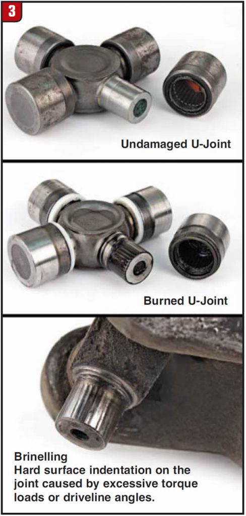
Scrutiny of the U-joints is the easiest and most crucial inspection in the driveline. If retaining clips are used, all should be present and in good condition. There should not be excess play; any play that can be visually spotted at the joint while twisting the driveshaft back and forth by hand is impermissible, as this is a sign of interior damage (Figure 3). Inspect for torn seals or rust-colored dust that may betray a dry joint. Ensure the U-joints move freely without binding in all directions. Use a quality U-joint and proper tools when replacement is required.
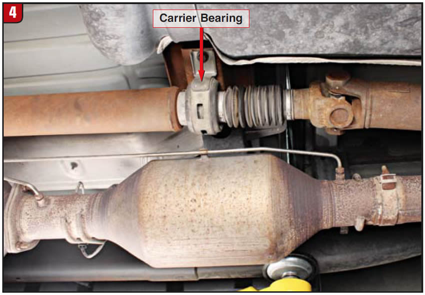
With a two-piece driveshaft, check the carrier bearing for excess play as well (Figure 4). Look for signs of dry rotting or cracking in the bushing material. Carrier bearing noises tend to travel through the chassis; make sure a test drive to listen for telltale carrier bearing noise is carried out.
Whether you do it for up-sell profit or simply to head problems off at the pass, this basic checklist for driveline inspection is a good hedge to avoid future problems. The few extra minutes a driveline inspection takes will help you address reputation-tarnishing problems before they leave the shop, minimizing comebacks and increasing customer satisfaction.
Devin Gallagher is a Sonnax product development manager for driveline and transmission components. He is a member of the Sonnax TASC Force (Technical Automotive Specialties Committee), a group of recognized industry technical specialists, transmission rebuilders and Sonnax Industries Inc. technicians.


