


A vehicle comes into the shop for repairs due to a severe slip in reverse or no-move condition in reverse. In some cases, upon disassembly the cause is not readily identified and the unit is rebuilt without correct-ing the problem. Obviously the transmission is installed into the vehicle exhibiting the original no-reverse complaint.

When an application chart is used to diagnose the no-reverse complaint, it is noticed that three elements need to apply to complete a reverse gear: the reverse clutch, the low/reverse clutch and the low clutch
(Figure 1).
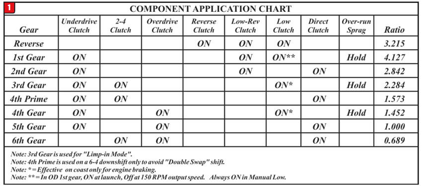
At first glance the low clutch seems to be used in other forward gears, and since all forward gears are operational the low clutch is not considered. This may prevent a thorough inspection of the low clutch located on the centerline shaft. Additionally, because the low/reverse clutch is used for first and reverse, this too is not seriously considered. As a result, the reverse clutch appears to be the most likely candidate and great effort goes into locating a problem within its operation yet none is found. This has led some technicians to change the entire UD/OD/Rev. clutch housing assembly along with a solenoid and valve body assembly as a solution but the desired result is not achieved.
The cause is a problem with the low clutch. Although it is used in some forward gears, it is only applied during certain driving conditions. The overrunning sprag is the primary holding device to complete first, third and fourth gears. The low clutch is applied when additional holding capacity is required as well as for engine breaking. This low clutch-housing drum is known to crack or blow out the 0.020” air bleed capsule (#202 in Figure 2).
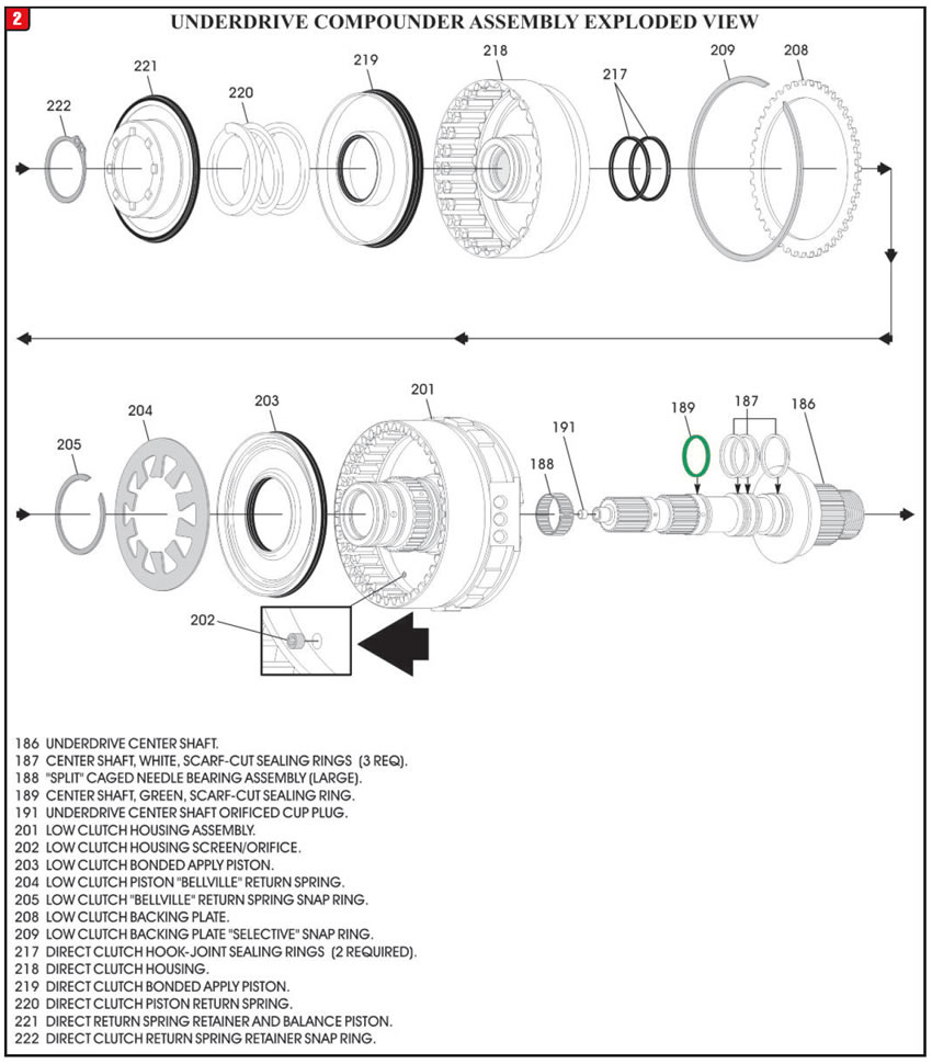
Some of these orifices were not properly staked into place. When it works its way out of the bore it causes a large enough leak to prevent the clutch from applying or burning it.

If the screened orifice capsule is located and is not damaged, it can be reused if staked back in properly. If it’s damaged, you will need to fabricate one to save the housing, as this orifice is not sold separately.
Finding a good used low clutch housing is not easy either as this is the housing with the Direct Clutch sealing rings on it. The rings wear into the housing enlarging their grooves. When this occurs, instead of having a nice first to second shift it either flares or goes to neutral. Since this is a common problem, good used housings can be difficult to locate. Brand new from the dealer now come fully loaded for approximately $360.
One word of caution, on a few occasions technicians have accidentally placed the valve body gaskets on backwards (Figure 3).
INCORRECT PLACEMENT OF VALVE BODY GASKETS
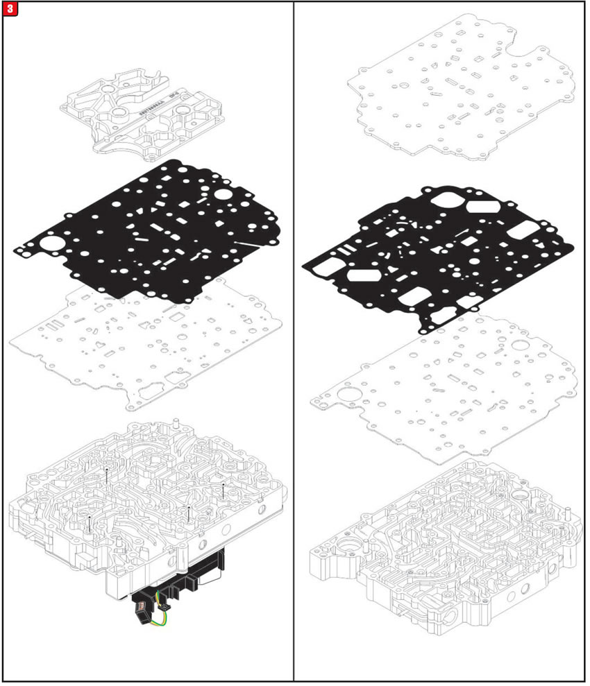
A line pressure check indicates that line pressure is good in park and neutral, but low in drive and reverse. This will cause the vehicle to have delayed engagements and it will slip badly in all gears. Figure 4 shows the correct placement of the gaskets.
CORRECT PLACEMENT OF VALVE BODY GASKETS
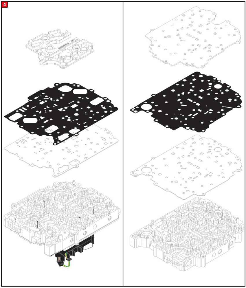
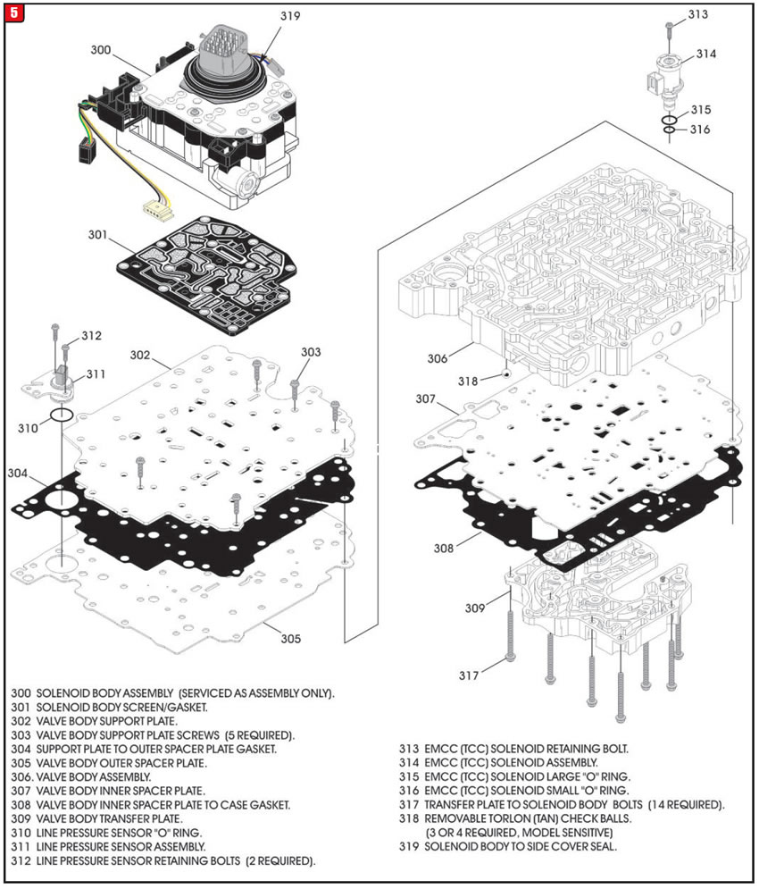
Figure 5 shows a breakout view of all the valve body parts and placements.
COMPLETE VALVE BODY EXPLODED VIEW


After repairing or rebuilding a Continuously Variable Transmission used in Jeeps, Dodge, Nissan or Mitsubishi vehicles a P0721, Output Speed Sensor Performance and/or P0722, or Output Speed Sensor No Signal code may set shortly after launch. If driven long enough, a P0730 Incorrect Gear Ratio code may also set.
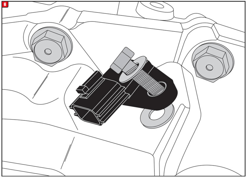
Various applications require one or more shims under the output speed sensor to maintain proper air gap between the sensor tip and signal gear (Figure 6). If the shim or shims are left off, or are placed between the attaching bolt and sensor, the tip of the sensor rests upon the signal gear. Once the gear is in rotation it damages the tip of the sensor and the signal is lost.

The output rpm sensor measures the output gear integral to the output side of the secondary pulley thereby providing secondary pulley rpm readings to the TCM. This signal can also be used for an output speed signal.
The output gear on the secondary pulley drives a reduction gear assembly, which in turn drives the differential ring gear. Due to a variety of applications there becomes a variety of different overall gear ratios. These ratio differences change the diameter of the output gear the sensor reads. Since the output speed sensor length remains the same in all applications, to retain the proper air gap between the tip of the sensor and the gear, a shim or shims are used under the sensor to accommodate larger diameter gears.
A gear diameter small enough where the speed sensor does not require a shim will have an approximate .040” air gap.
The next larger diameter gear would require a .040” shim under the sensor to provide that approxi-mate .040” air gap and so on.
If the shim or shims were incorrectly installed between the bolt and sensor, replace the sensor and install the shim or shims between the case and sen-sor.
If the shim or shims were not installed, replace the sensor an install the appropriate number of .040” shims under the output speed sensor.
If you are not certain the number of shims required, measure the distance from the highest point on the output gear to the surface area on the case where the output speed sensor bolts to.
The length of the speed sensor is approximately 1.140”. If the depth of the speed sensor hole measures approximately the same as the sensor length, install one .040” shim under the sensor. If it measures approximately 1.100”, place two .040” shims under the sensor. If it measures approximately 1.180”, no shims are required.

Nissan part number for .040”
shim…………………………….08915-4361A

June 2019 Issue
Volume 36, No. 6
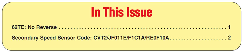
- 62TE: No Reverse
- Secondary Speed Sensor Code: CVT2/JF011E/F1C1A/RE0F10A


