

It’s hard to believe that the 6L80/6L90 transmissions have been on the road for a decade and, due to the vehicles that they’re used in, they are showing up in increasing numbers for repair. As with any transmission family, there have been issues requiring certain components to be redesigned. Some components are changed only slightly with other changes being more involved.
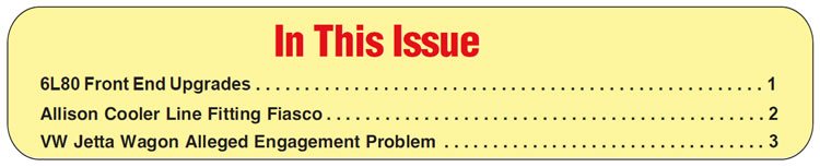
Early on, there was an issue with inconsistent clutch apply, concerning the 1-2-3-4/3-5 Rev clutch drum assembly and the pump-cover sealing rings. For whatever reason, the sealing rings would not energize consistently under all conditions, resulting in slippage of either clutch. The fix that GM chose was a throw-back to 1987 and the 440T4 transmission, although it involved the pump cover instead of the driven sprocket support (Figure 1).
Back then, everyone marveled at a new sealing-ring material made by DuPont called Vespel, which sealed by compression instead of being energized like any other sealing ring. The design, at first glance, made it appear that the stationary rings would wear down in no time, but history has proven otherwise. The same approach made to the 6L80 pump cover, so far, has met with the same success.
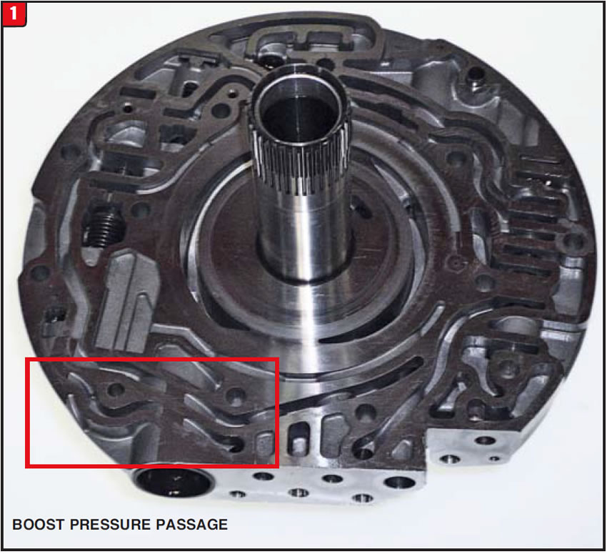
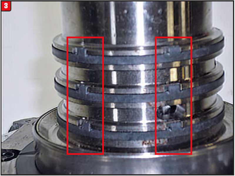
Unlike other transmission families that have had several different pump covers to deal with, the 6L80/6L90 pump cover options were minimal resulting in one part number that fits all (24248573). The main change to the upgraded cover has to do with the sealing-ring tower (figures 2 & 3). The sealing-ring groove depth was modified slightly, and the groove side-walls were notched to accept the lock tabs on the sealing rings.
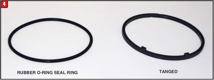
Unlike the 440T4 driven sprocket support sealing-ring design that used rubber quad rings under the Vespel rings, the 6L80 pump cover design uses O-rings instead (Figure 4). Quad rings, after all, are fairly expensive to produce versus a simple O-ring, although both do provide the compression needed for the ring to seal.
Another issue that has plagued the GM six speeds has been cross leaks between the bell housing and pump cover, which resulted in erratic application and line-pressure problems. Beyond that, there has been a fair amount of pump rotor failures on 6L80 and 6L90 transmissions possibly due to pressure spikes.
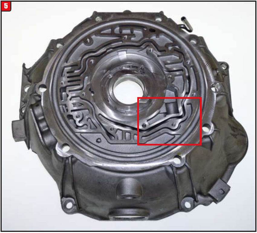
Depending on year and vehicle model, there has been several different bell housing casting numbers produced although they were all basically the same with the exception of Corvette, of course. Appearance wise, there is little difference between applications that enabled GM to roll all the previous designs into one (Figure 5). Except Corvette, the upgraded part number that will work on the 6L80 and 6L90 applications is 24248031 and is currently fairly inexpensive.
Aside from the few subtle external differences between previous model bell housings and the new upgraded version, a change was made to an oil passage (worm track) responsible for pressure regulator boost pressure. The oil passage on previous housings was continuous from one end to the other (Figure 6).
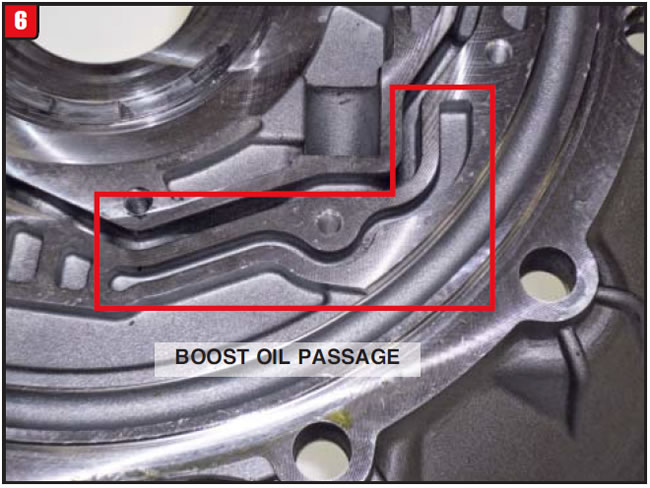
In order to reduce potential cross leaks that passage was modified somewhat. The oil passage in the upgraded bell housing is somewhat broken up making it appear as though the fluid might be restricted at a certain point (Figure 7).
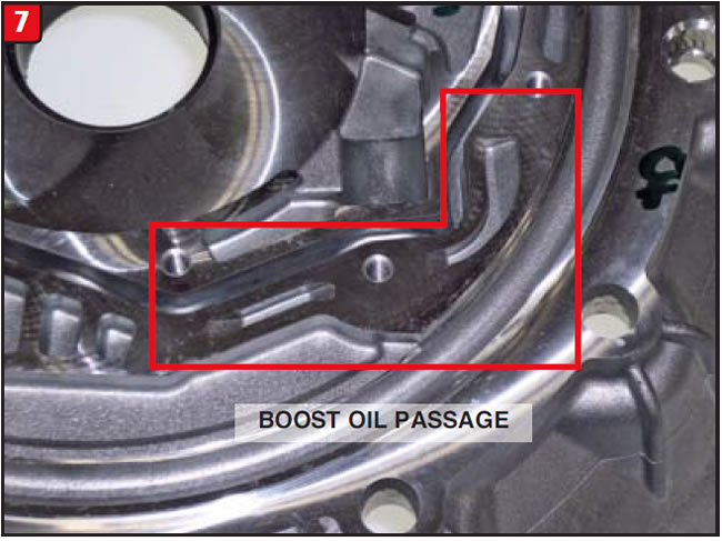
Although there is no pump plate (separator plate) between the bell housing and pump cover, oil passages in both components must line up correctly. At first glance the pressure regulator boost valve oil passage in the upgraded bell housing and old or new design pump covers could cause an interruption in oil flow of boost pressure due to the lack of the continuous track in both components. Actually, the blocked areas of the pump cover in Figure 1 overlap with the open areas of the bell housing in Figure 7 and vice versa, resulting in a continuous oil flow from the valve body to the boost valve. This arrangement supposedly minimizes the potential for cross leaks. Time will tell.
The same modification has also been done over the years to other transmission types including the venerable TF6 with Chrysler eliminating one of the three finger worm tracks in the pump body to also minimize cross leaks. Who’s to say old fixes can’t work today.


Allison has provided a wealth of different transmission models for decades to accommodate various on-highway and off-highway vehicle requirements, mainly medium duty and heavy duty. With the addition of the 1000 and 2000 series of transmissions, Allison was able to enter the light-duty truck market as well, beginning with Chevrolet.
As with other transmission types, Allison has implemented several component upgrades to the 1000 family of transmissions, some major and some minor. When it comes to design changes, no part is untouchable, as is the case with the 1000 series cooler lines and cooler line fittings, affecting both the transmission and radiator ends.
When it comes to cooler systems, Allison is unequaled, especially on heavier-duty applications such as the MD and HD family of transmissions. To accommodate commercial applications Allison has a variety of different cooler and cooler-line configurations. Fortunately, the 1000/2000 series cooler systems are much more basic, with Chevy applications comparable to other regular transmission types. There are, however, commercial applications that require a separate manifold for the cooler lines, which is attached to the bell housing. Although the 1000 design is simpler, relatively speaking, several variations have occurred since the transmission was launched.
Major changes to the cooler system on the 1000 series of transmissions center on the diameter of the cooler-line flare and the diameter of the cooler-line fitting threads. As with most later-model cooler lines and fittings, the Allison 1000 uses a push-in design. The changes were made to enhance the flow rate of the fluid going to and from the radiator. Beyond the fittings used for production transmissions, Allison also provides certain fittings in order to adapt one transmission design level to a different cooler-line flare diameter. Not only was the cooler-line flare diameter affected, but the related flare diameter in the fitting was modified as well. O-ring diameter is uniform among all fitting designs.
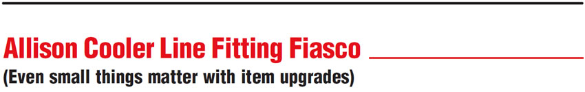
As a starting point when the 1000 was released, both cooler-line fittings were fairly standard, big but standard looking (Figure 8). The hole going through the fitting to handle the flow rate is 0.500 in diameter which resulted in a 3⁄4” pipe thread. The bore of the fitting that accommodates the cooler line flare is about 0.870 in diameter and uses an orange clip (Type 1). The width of the 11⁄4” hex body is approximately 0.500. The OE part number is 29540501.
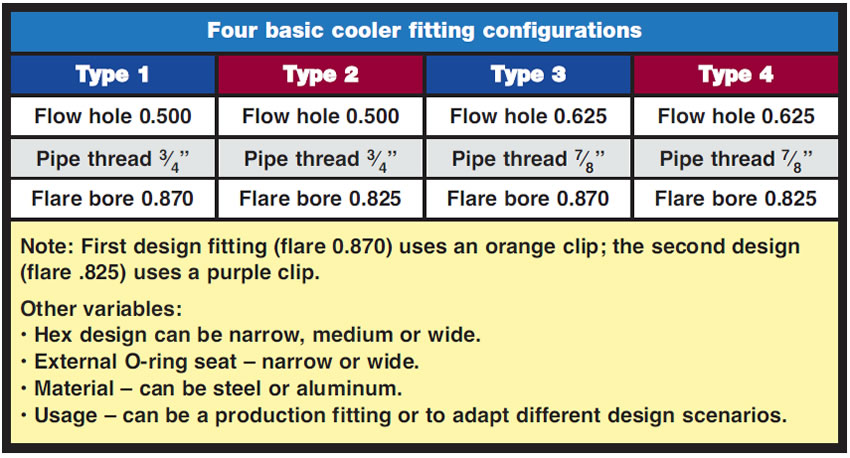
By 2003, things started to get ugly, from a component standpoint that is. It was at this time, when Allison started to implement changes with the cooler circuit, although the changes occurred at different intervals depending upon application. There are four basic cooler-fitting configurations to contend with, along with other more subtle variations. Beyond that, there is the issue of whether the fitting is for the transmission or the radiator. The basic types are set forth in the table at right.
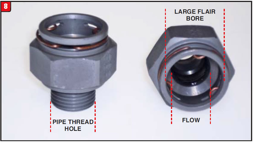
One change that started to occur in 2003 had to do with the reduction of the cooler-line flare diameter. To accommodate the change, a new fitting was released with the modified bore at the line-flare area (Figure 9). The new fitting, which can be referred to as Type 2, retained the 3⁄4” pipe thread (0.500 flow), but uses the 0.825 flare bore and has a purple clip. The new fitting also has a wider body than the previous fitting and both designs are steel. The OE part number is 29541729.
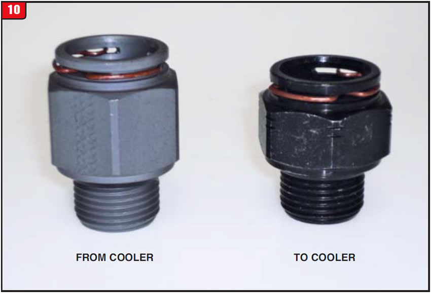
During this period and due to the changes that were being implemented, there was a concern about interchangeability between certain transmission and vehicle models; therefore, Allison released a cooler fitting kit to address the issue. The kit actually contains two cooler fittings that have a Type 3 design. The purpose of the kit is to adapt transmissions with the larger fluid-flow hole and related 7⁄8” pipe thread to a vehicle with the first-design cooler lines that have the larger diameter flare. Both fittings have orange retainer clips (Figure 10). The fittings are steel, but there are two different lengths. The long body fitting is for the cooler return line and the medium length body is the to cooler-line fitting. The kit OEM part number is 88996640; however, the individual fittings are not available separately.
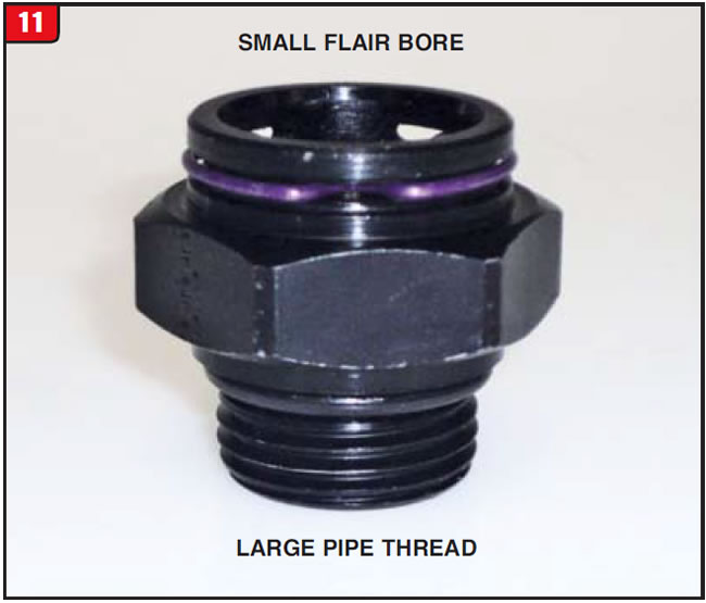
By the end of 2003 and the beginning of 2004, most vehicle models were switched over to the new format, which can be considered the Type 4 design. The fittings used have the larger 7⁄8” pipe thread and reduced cooler line flare diameter (Figure 11). The fitting has a purple retaining clip due to the smaller diameter flare. The width of the hex is narrow and the fitting is steel with a narrow external O-ring seat. The part number is 15170226.
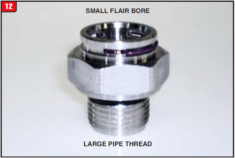
Another fitting variable that Allison released was also for adaption purposes. The fitting would also be considered a fourth design like the fitting shown in Figure 11, with a couple of distinctions.
One difference is that the fitting is aluminum and has longer threads (Figure 12). Another difference has to do with the area around the external O-ring, which on this fitting has a wide O-ring seat. The part number, 88996645, denotes a kit, although it only contains one fitting and one instruction sheet.
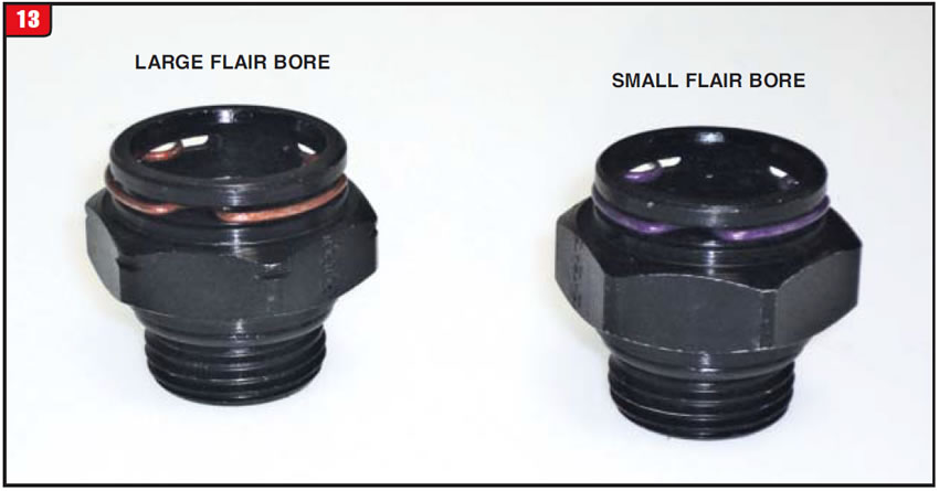
On the radiator side of the fence, changes were also made to the cooler-line fittings. Earlier model applications can also use a Type 3 design like the transmission fittings, with one variable. Unlike the two transmission fittings contained in kit number 88996640, the body of the radiator fitting is narrow (Figure 13). The radiator fitting on the left of the illustration looks like the later model transmission fitting on the right, with one exception. This fitting is for the first design, large diameter flare cooler line, which is why it has an orange retaining clip. The OE part number is 89040281.
Another radiator cooler-line fitting used on later models has a little wrinkle that transmission cooler-line fittings do not. Due to the radiator-support design, an extra feature was added to the cooler fitting to aid in assembly. A Belleville washer is crimped onto the fitting (Figure 14).
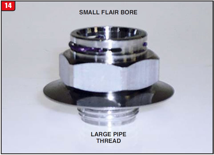
The washer helps to tighten the radiator against the support, and it is advisable to change the fittings one at a time in order to keep everything in place. Without the washer, the fitting is made somewhat like the transmission fitting in Figure 12 as far as material and type; however, there are subtle differences.
It remains to be seen how many more concoctions may surface, although one fact does exist: There will always be more changes.


The owner of a 2005 VW Jetta arrived at the shop with an erratic engagement issue. The problem centered on what appeared to be a delay when shifting the transmission from park to drive. The customer was unsure about exactly when and how it occurred, but felt that it mainly happened when he first fired up in the morning.
The vehicle was a Jetta Wagon equipped with a 2.0L engine and a 01M (AG4) four-speed automatic transmission. Considering that the Jetta was 11 years old, it only had 73,000 miles on it and was a second-owner vehicle. Overall, the vehicle was in great shape and ran well.
Although there was no check engine light, the vehicle was taken for a thorough road test with a scanner connected just to see if everything was working as it should, as well as to look for any previous codes. No codes were found. Since the problem seemed to occur when the engine was cold, the vehicle was left at the shop overnight in order to drive it the next morning. The car was left outside overnight due to the fact that the car owner always parked outside, just to ensure that the conditions were the same.
First thing the next day the engine was started and the transmission was placed into drive, and of course application was immediate with no sign of a slip or hesitation. The vehicle was road tested again to make sure that it worked well cold just like it did the day before, which it did. After consulting with the customer, it was decided to keep the vehicle for another day and to try it again cold.
As luck would have it, when the vehicle was fired up and placed into drive that following morning, the transmission did hesitate going into gear just as the customer had experienced. The question became, which transmission component was causing this erratic condition and only when cold?

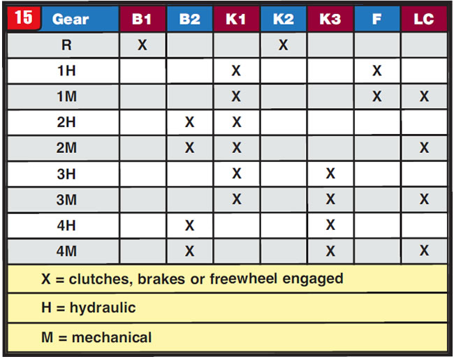
This type of issue could be caused by a variety of different conditions such as a sticky valve in the valve body, sealing rings that don’t energize or a clutch piston that doesn’t seal. The area of concern in the 01M was the K1 clutch, which is applied in first through third gears (Figure 15).
Normally, when clutch application is inconsistent due to one of the stated conditions, the slip or hesitation would occur more frequently than was happening on the Jetta. In addition, other shift modes affecting the K1 clutch such as a 4-3 kick down downshift worked well with no sign of slippage. The fluid condition was also in good shape indicating a lack of an internal slip condition.
Just for kicks and giggles, a search was done for any TSB’s or recall notices and, sure enough, one popped up relating to this particular vehicle. Bulletin number Group 37, NO. 07 – 04 (2001948) refers to excessive engagement time when shifting from park to drive. This issue is part of what VW calls “Cold Neutral Control.”

The reason that the hesitation seemed erratic on this Jetta is due to how the cold neutral control strategy is supposed to work. If the vehicle is equipped with the cold neutral feature, nothing much can be done about it other than making sure that the parameters are correct and informing the car owner as to how the vehicle is to function.
Vehicles equipped with the cold neutral control feature that can exhibit this unique shift characteristic are: 2002-05 Cabrio, Golf, Jetta, New Beetle containing the 2.0L engine with ULEV (ultra low emission vehicle) and the 01M transmission.
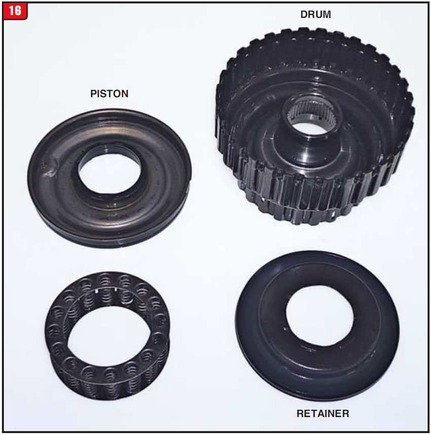
The purpose of cold neutral control allegedly is to help to warm up the catalyst and thus reduce emissions. This is accomplished by not applying the K1 immediately, which basically keeps 16 the transmission in neutral until certain conditions are met. The K1 clutch used in the 01M is the second design, which is substantially different from the first design used in the 095 (Figure 16). Normally, when the transmission is put into drive the clutch applies immediately, which loads the engine and increases emissions. It is questionable as to the impact on emissions during this brief period. Another concern is clutch application feel once the K1 does apply after the vehicle has a fair amount of miles on it.
Cold neutral control will only activate under the following conditions:
- Transmission fluid temperature must be below 40C (ambient temperature at that level can result in the feature working or not based upon a couple of degrees one way or the other).
- Brake pedal must be applied (transmission must apply immediately upon pedal release).
- Accelerator pedal must not be applied.
- Transmission is shifted into drive for the first time (the feature should cancel thereafter).
Cold neutral control will only reactivate once the above conditions are met.
The condition exhibited on the 2005 Jetta is just another example of potentially chasing a ghost instead of determining what beyond the transmission can cause an engagement problem.

June 2016 Issue
Volume 33, No. 6
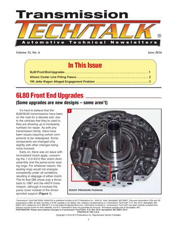
- 6L80 Front End Upgrades
- Allison Cooler Line Fitting Fiasco
- VW Jetta Wagon Alleged Engagement Problem


