


A vehicle equipped with a 4F27E or FNR5 may have a complaint of a badly slipping or no reverse condition. The vehicle may have come in with this complaint and can still have it after overhaul.

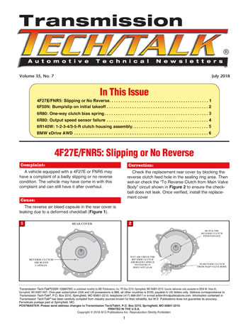
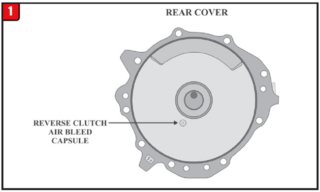
The reverse air bleed capsule in the rear cover is leaking due to a deformed checkball (Figure 1).

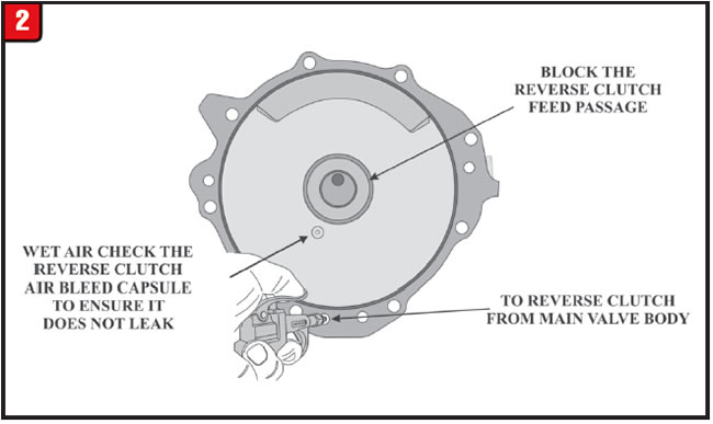
Check the replacement rear cover by blocking the reverse clutch feed hole in the sealing ring area. Then wet-air check the “To Reverse Clutch from Main Valve Body” circuit shown in Figure 2 to ensure the check-ball does not leak. Once verified, install the replacement cover.


Certain Ford and Lincoln vehicles (see service information) equipped with the 6F50/55N may have a complaint of a sluggish initial takeoff in drive followed by a harsh bump or slip.
Note: This bulletin applies only to the listed vehicles that have MERCON LV® on the dipstick.
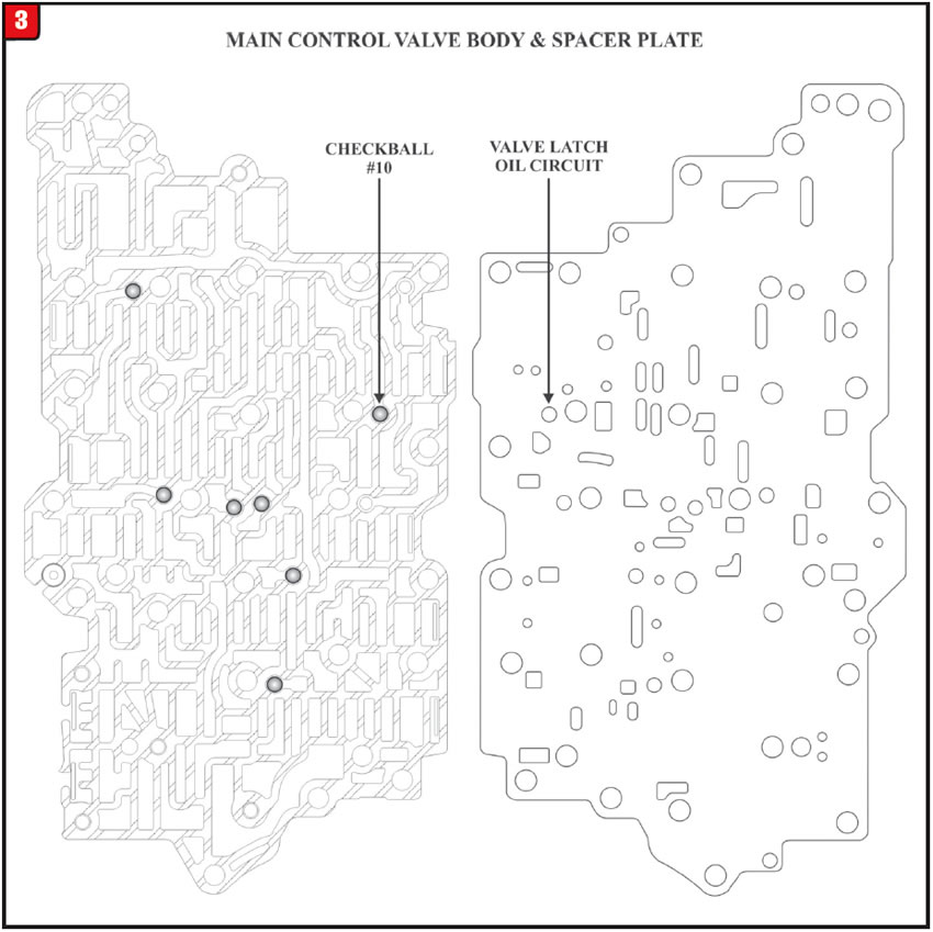
A combination of computer programming and a hydraulic problem in the valve latch oil circuit.
Valve latch – pressure supplied to the multiplex shift valve from the low/reverse/overdrive (4-5-6) regulator valve.
This modification is directed at the #10 checkball located in the main control valve body as well as the valve latch feed hole in the main control spacer plate both of which can be seen in Figure 3.
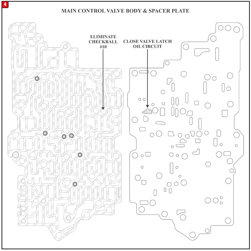
Eliminate the #10 checkball and close off the valve latch feed hole in the spacer plate as shown in Figure 4.
Reprogram the PCM to the latest calibration using IDS release 73.04 or higher.
The following vehicles that were built on or before April 15, 2011, are subject to these modifications:
- 2010-2011 Ford Taurus
- 2009-2011 Ford Edge
- 2011 Ford Explorer
- 2010-2011 Lincoln MKS
- 2009-2011 Lincoln MKT & MKX

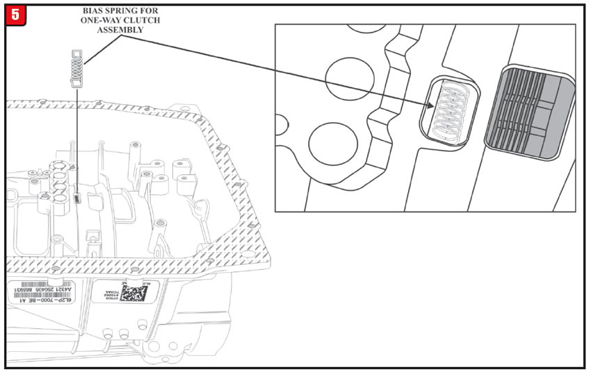
When the transmission pan is removed from a 6R80, the technician notices an odd looking spring laying in the bottom of the pan. No one seems to know where this spring came from or where it goes (Figure 5).
When the 6R80 was updated during the 2010 model year, a one-way diode style clutch was installed. The bias spring goes between a lug of the one-way clutch and the transmission case (Figure 6). This puts tension on the diode assembly to keep it from “clunking” during transmission operation.
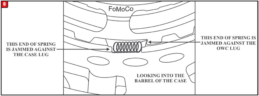
Install the bias spring as shown in figure 6 on all 6R80 transmission that are equipped with a one-way clutch.


Certain Ford and Lincoln vehicles (see chart provided below) may experience an intermittent failure of the output speed sensor, which is part of the molded lead frame that is bolted to the valve body. This failure could result in an unintended downshift to first gear. Depending on vehicle speed at the time of the down-shift, an abrupt wheel speed reduction may occur which could cause the rear wheels to lock.
A defect in the molded wire frame assembly (Figure 7).
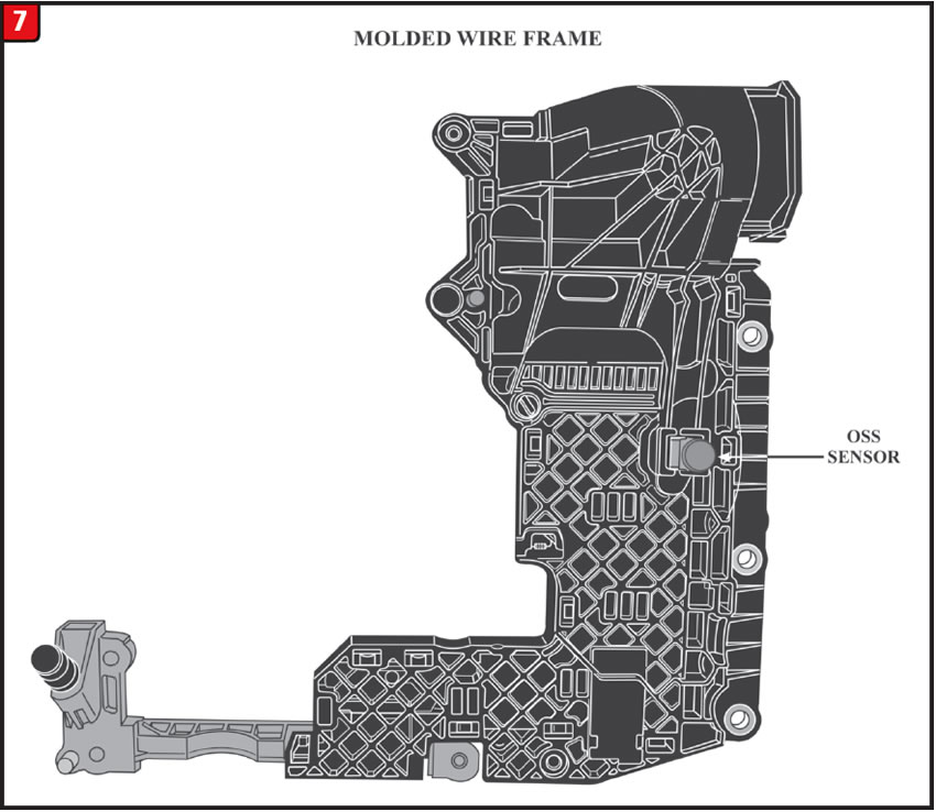
This molded wire frame assembly replacement is covered under a Ford customer satisfaction program 16N02.

The chart provided identifies which vehicles are covered under the customer satisfaction program:

Disassembly and reassembly of the 1-2-3-4/3-5-reverse (direct drum) piston and retainer has been confusing in many shops.
In most applications where a clutch apply piston is retained by a snap ring, it is customary to use a pair of snap ring pliers to expand the snap ring in order to remove the internal parts. The 6R140W drum is the exception; the disassembly procedure is opposite.
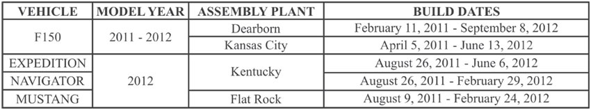
First use a spring press to hold the piston and retainer down as seen in Figure 8.
Next, use two (2) flat bladed screwdrivers held 180º apart and PUSH IN on the snap ring as shown in Figure 8. When the snap ring is pushed in far enough, release the press and the piston and retainer can now be removed.
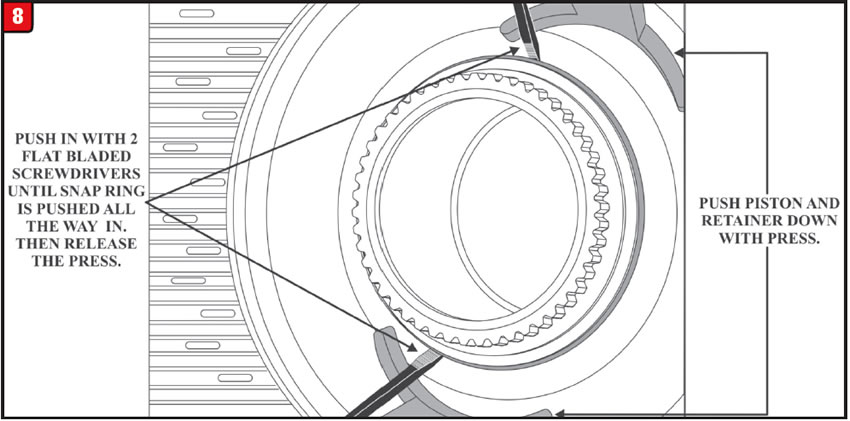
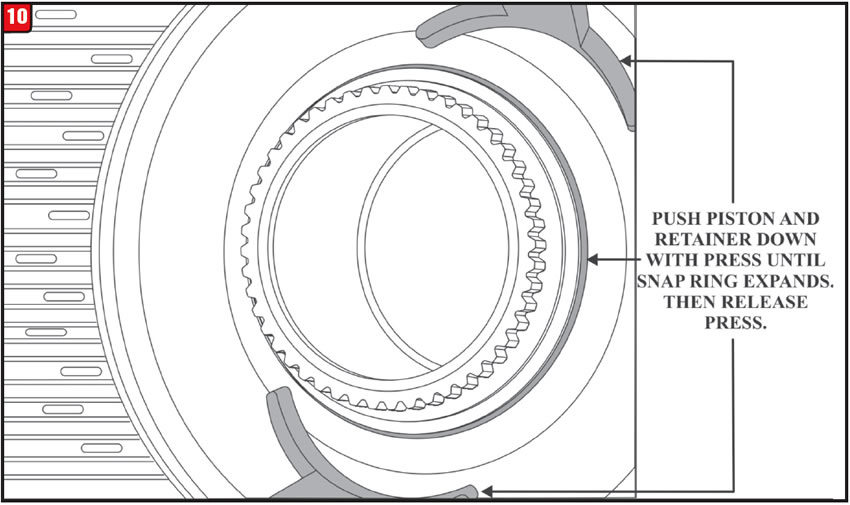
The inside diameter of the piston retainer is tapered on the backside as seen in Figure 9. When it is time for reassembly, install the piston into the bottom of the drum. Then place the piston retainer on top of it and simply use the press to push the retainer down.
Watch for the snap ring to expand as shown in Figure 10, then release the press. The drum is now ready for further assembly.


A 2008 BMW 328Xi AWD comes into the shop with the ABS, traction control and brake warning lamps illuminated. The Driver Information Center displays warning messages such as “Worn Brake Pads” and “Faulty Wheel Speed Sensors.” Scan tool code retrieval displayed a 5F3A DTC the definition of which is “Transfer Case Malfunction.” A grinding noise was also present which appeared to be coming from the transfer case area.

The transfer case in these AWD vehicles cannot even be seen until part of the exhaust system is removed and the protective skid shields are removed. With the shift motor removed and still electrically connected, the vehicle was started and the shift motor drive gear was held by hand. The motor began to cycle but the drive gear could be held from turning at this time the grinding noise could be heard coming from the shift motor.
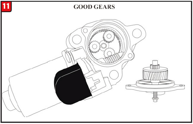
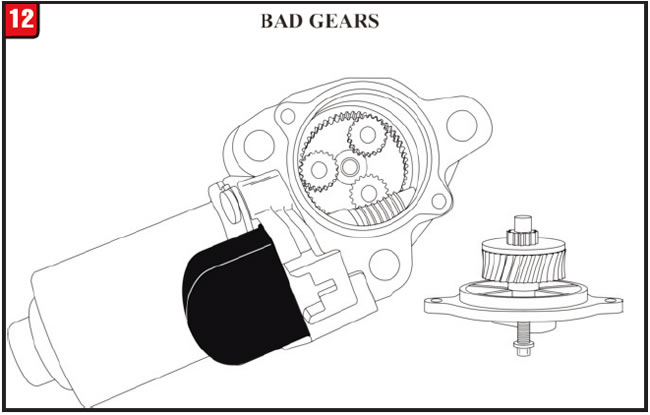
Once the shift motor was disassembled, stripped and “apple cored,” gears could be seen as shown in Figure 12. A good shift motor is shown in Figure 11. This shift motor failure is what generated the transfer case malfunction code as well as the appearance of the above-mentioned warning lamps.
It was now apparent that this xDrive ATC 300 (Active Torque Control) system works in conjunction with the vehicle’s Dynamic Stability Control System.

Replacement of the transfer case shift control motor fixed all complaints.

The following information will explain the principles of operation for the xDrive AWD system:
VTG Actuator Motor & Incremental Sensor: The VTG (Transfer Case Control Module) actuator motor responds to the incremental sensor in the motor that records the adjustment rate and position of the actuator motor shaft. The recorded data is necessary to activate and control the multi-plate clutch that controls torque distribution to front and rear axles.
Classification Resistor: The locking torque characteristic curve of the multi-plate clutch may vary slightly due to mechanical tolerances during the manufacture of mechanical components. The actual characteristic curve for a transfer case is recorded by means of a clutch test after assembly.
This characteristic curve is compared with the characteristic curves stored. The best possible characteristic curve is selected. Each characteristic curve stored has a classification resistor and identifier. After completion of assignment the classification resistor is installed on the shift control motor. Refer to Figure 13.

In the vehicle, the resistance value is imported from the VTG Control Module. The software automatically sets the established characteristic curve. This setting is made or checked whenever the engine is started.
NOTE: When replacing the VTG actuator motor, remove the classification resistor from the damaged motor and install it on the replacement motor so that the programmed characteristic curves remain with the vehicle to insure proper transfer case operation.
Calibration Sequence: A calibration sequence is run when the ignition is turned OFF. During this calibration sequence, a certain angle setting of the VTG actuator motor has a corresponding locking torque assigned. The effects of wear are also taken into account when this is done.
The multi-plate clutch is closed fully and separated once during this reference run. When this happens, the current draw is measured at the respective angle setting of the VTG motor. This determines the beginning and end of the closing movement for the multi-plate clutch. The angle setting is recorded by means of the incremental sensor in the VTG motor assembly. These values are stored and are used as data when the car restarts.
When the VTG motor is running, the control cam turns and pushes apart the two control levers. Depending on the angle of rotation, the ball ramps will convert the rotation movement into an axial force. This axial force of the actuator lever pushes the multi-plate clutch plates together.

July 2018 Issue
Volume 35, No. 7
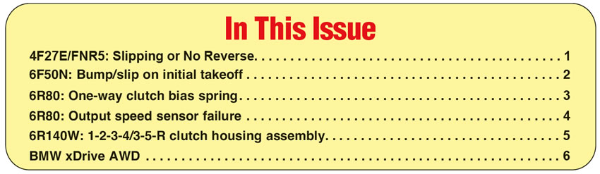
- 4F27E/FNR5: Slipping or No Reverse
- 6F50N: Bump/slip on initial takeoff
- 6R80: One-way clutch bias spring
- 6R80: Output speed sensor failure
- 6R140W: 1-2-3-4/3-5-R clutch housing assembly
- BMW xDrive AWD: Transfer case and grinding noise


