

Issue Summary:
- A 2000-up Nissan vehicle with the RE4R01A or RE4F04A has a complaint of a slightly delayed 1-2 upshift and a quick over-speed or cut-loose on the 2-3 shift.
- A Subaru vehicle with the 4-EAT-Phase II may exhibit a slight delayed forward engagement and will have no reverse. When the engine is shut off the vehicle lurches backward.
- A Mitsubishi vehicle with the F4A51 transaxle has no forward movement when the headlamps are turned on.
- Before or after overhaul, a Nissan/Infiniti with the RE5R05A may exhibit various upshift complaints.


A Nissan vehicle equipped with either the RE4R01A or RE4F04A transmission enters the shop with a complaint of a slightly delayed 1-2 upshift and a quick over-speed or cut-loose on the 2-3 shift. This condition may be confused with a high-clutch failure. Upon disassembly, no problems are apparent in the high-clutch circuit.

One cause may be a stuck-closed WOT (wide-open-throttle) switch. On 2000 and later models, a stuck-closed WOT switch not only causes the slightly delayed upshifts (about 4-5 mph) into all gears – 1-2, 2-3, 3-4 and TCC apply – but also causes shift solenoid A to be energized briefly immediately before the 2-3 upshift command. When this takes place, the transmission instantly makes a shift from 2nd gear back to 1st (which feels like a cut-loose, or over-speed), then completes the rest of the upshifts.
Note: Nissan models previous to model year 2000 do not exhibit the same condition. A stuck-closed WOT switch would cause high line pressure and excessively late upshifts in all ranges.

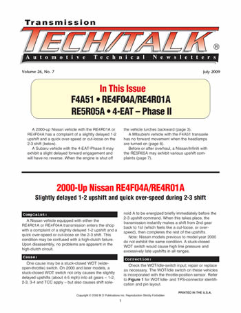
Check the WOT/idle-switch input; repair or replace as necessary. The WOT/idle switch on these vehicles is incorporated with the throttle-position sensor. Refer to Figure 1 for WOT/idle- and TPS-connector identification and pin layout.
Checking idle/full-throttle switch:
Step 1:
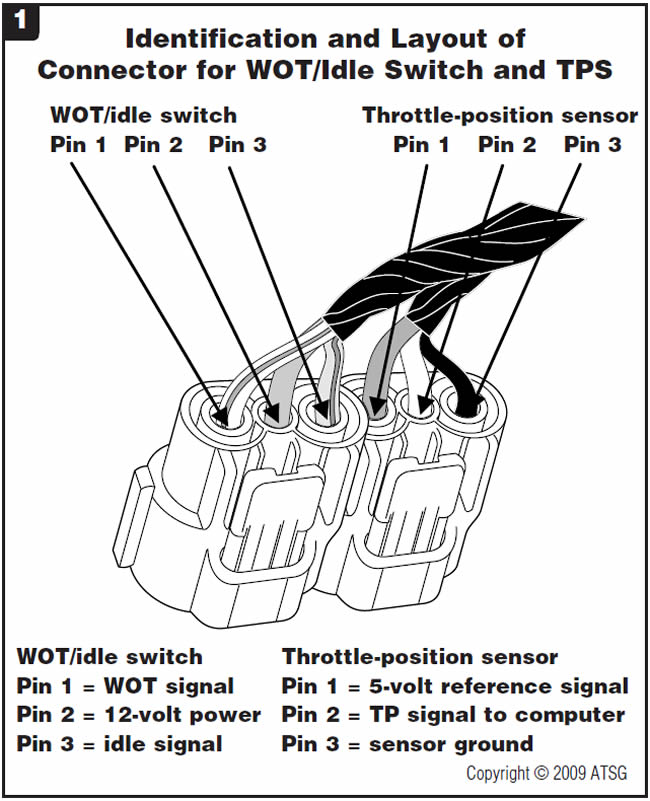
This step checks for battery reference voltage to the WOT/idle switch. Turn the ignition on. Probe the wire side of the WOT/idle-switch harness with the connector plugged in, and check for voltage at pin 2 of the WOT/idle throttle-switch connector. Place the red lead of your voltmeter to pin 2 and the black lead to a good ground such as the battery negative terminal. You should see a reading of about 8-12 volts DC with the ignition on (Figure 2).
Step 2:
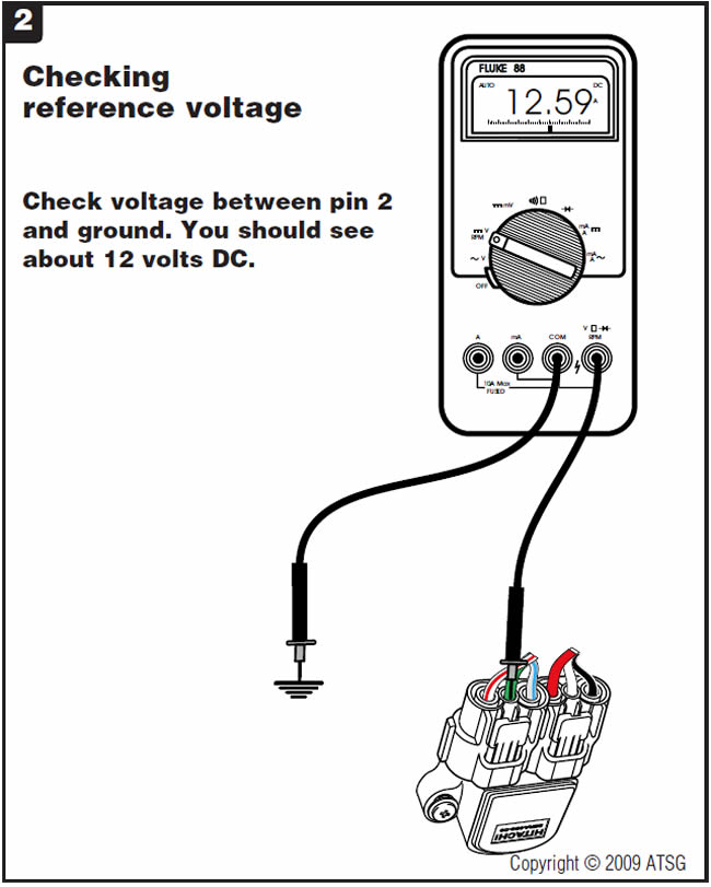
This step checks the idle side of the WOT/idle switch. Move the red lead of your meter to pin 5 of the connector. Leave the black lead on the battery negative terminal. You should see a reading of about 8 to 12 volts DC with the ignition on and accelerator pedal at closed throttle. As the accelerator pedal is depressed, the voltage should drop to about 0.0 volt DC (Figure 3).
Step 3:
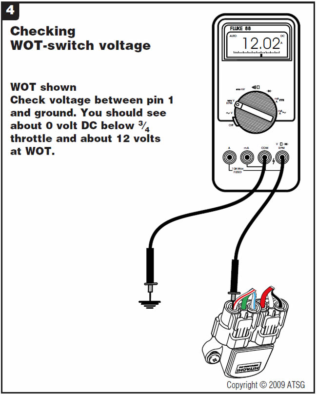
This step checks the WOT side of the WOT/idle switch. Move the red lead of your meter to pin 1 of the connector. Leave the black lead on the battery negative terminal. Depress the accelerator pedal fully to the floor. You should see a reading of about 0.0 volt DC at closed throttle. The voltage should jump to about 8 to 12 volts DC once the accelerator pedal has been depressed to between 5⁄8 and 3⁄4 throttle and should remain at the same voltage through wide-open throttle (Figure 4).
Step 4:
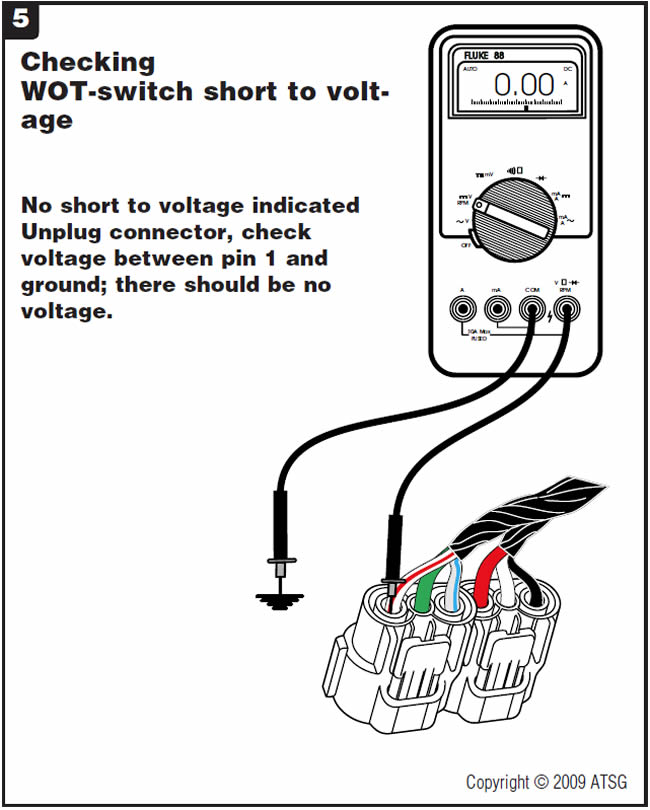
This step checks for a short to power on the WOT-switch wire. Disconnect the connector from the WOT/idle switch. Leave the red lead of your meter connected to pin 1 of the connector and the black lead on the battery negative terminal. You should see a reading of 0 volt. Any voltage on this wire would be an indication that the wire is shorted to power. If the wire is shorted to power, either locate the short in the harness or cut the wire at the computer and the WOT/idle switch and run a new wire (Figure 5).


The transmission may exhibit a slight delayed forward engagement and will have a no-reverse condition. When the engine is shut off the vehicle lurches backward.
The connectors for the low-clutch timing and pressure-control solenoids have been switched.
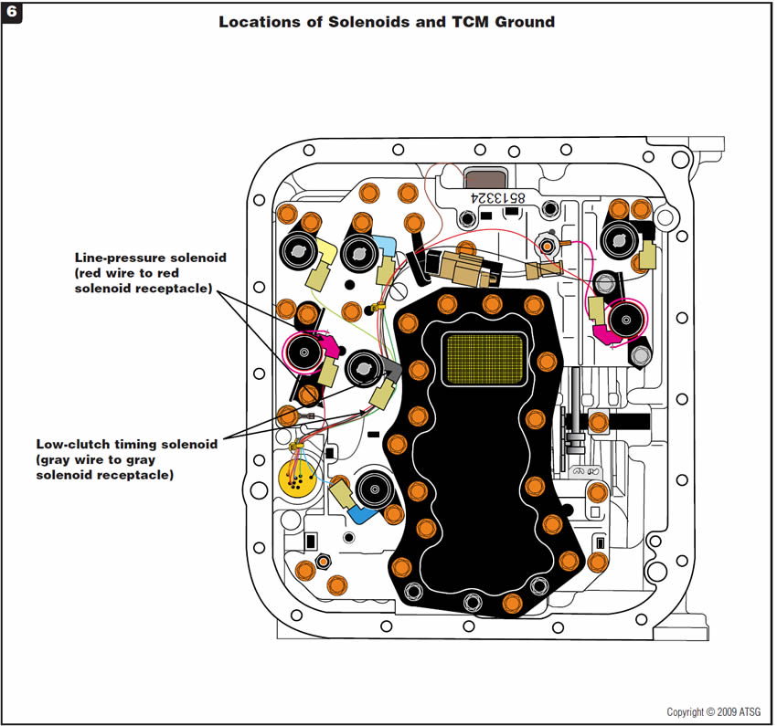
Because the pressure-control and low-clutch timing solenoids are close to each other, it is easy to switch their connectors. The connector ends are all the same color and are interchangeable; however, the wire color should match the solenoid connector. Refer to Figure 6 for solenoid identification.
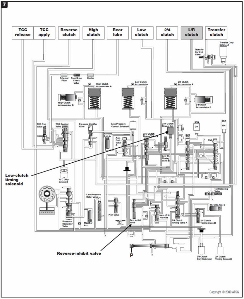
The no-reverse condition is a result of the low-clutch timing solenoid running all the time because the pressure-control-solenoid connector is plugged into it. This causes oil to stroke the reverse-inhibit valve
(Figure 7).
When the shift lever is in the reverse position and the engine is turned off, the low-clutch timing solenoid is also turned off. This drains the reverse-inhibit circuit, and the valve spring strokes the reverse-inhibit valve in the opposite direction. That momentarily charges the low/reverse-clutch circuit, causing momentary reverse engagement.
The combination of the low-clutch timing solenoid and the reverse-inhibit valve constitutes the reverse-inhibit system in these vehicles.
To prevent an accidental shift into reverse at a speed above 6 mph (10km/h), the low-clutch timing solenoid is turned on to stroke the reverse-inhibit valve, which blocks the low/reverse-clutch passage.


The vehicle has no forward movement only when the headlamps are turned on. The vehicle will move forward if the transmission is left in drive and the headlamps are turned off.
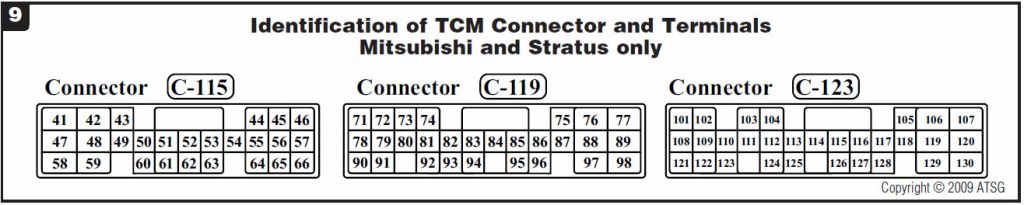
One of the tail lamps had a compromised ground. When the headlamps were turned on, voltage would seek a ground path through the reverse-lamp circuit. Looking at the wire schematic in Figure 8, you can see that when the selector lever is placed into the Drive position, the park/neutral switch will supply voltage to terminal 102 (Figure 9) at the TCM.
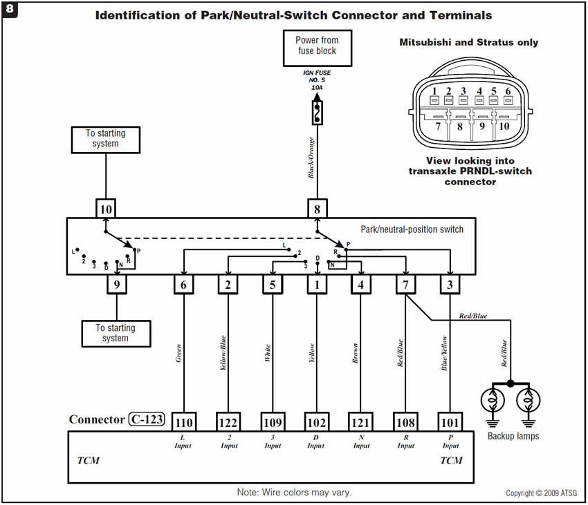
When the headlamps were turned on, voltage seeking a ground path through the reverse-lamp circuit would supply a signal to the TCM at terminal 108 as well. Then the TCM would believe that the transmission was in both Drive and Reverse and, as a safety feature, would energize the underdrive solenoid, preventing the underdrive clutch from applying and causing the transmission to obtain a neutral condition. This would explain why reverse was no problem, since that was the only signal the TCM received.
Repair the tail-lamp ground inside the trunk.

Before or after overhaul, a Nissan/Infiniti with the RE5R05A may exhibit various upshift complaints. Checking the vehicle with a scan tool reveals DTC P0720 Vehicle Speed Sensor A/T (revolution/output sensor).
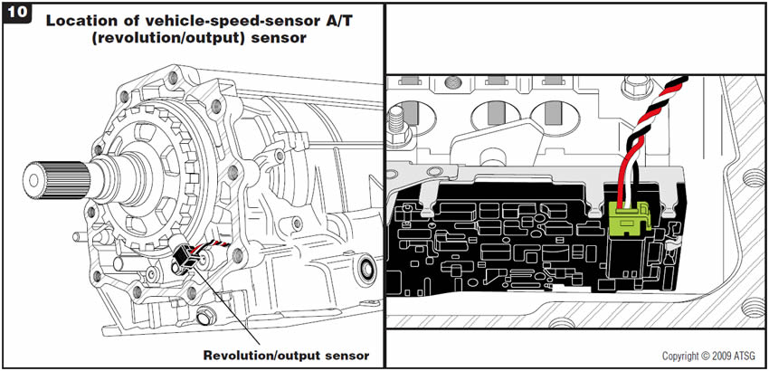
One cause may be a faulty vehicle-speed sensor (VSS) A/T (revolution/output sensor). The revolution/output sensor, a Hall-effect sensor in the rear housing of the transmission, obtains its reading from the park gear. The transmission control module (TCM) uses the revolution/output sensor to assist in determining shift scheduling.
DTC P0720 is set when the TCM doesn’t receive a proper voltage signal from the sensor while the vehicle is being driven. This code also can be set when the ignition switch is turned on and the TCM receives an improper signal from the VSS MTR before the vehicle begins moving.
The VSS MTR signal is sent from the instrument cluster/combination meter to the TCM by way of CAN (controller area network) bus signal through the CAN communication line. The instrument cluster receives its vehicle-speed information through the CAN communication line via the antilock-brake system from the wheel-speed sensors.
In the event of a malfunction of the revolution/output sensor, the TCM will use the MTR signal for vehicle-speed input.
Check the revolution/output sensor and replace as necessary.
Refer to Figure 10 for the location of the revolution/output sensor in the transmission and the harness-connector location on the park/neutral-position switch.
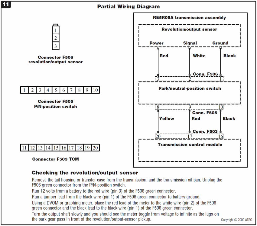
Refer to Figure 11 for a partial wiring diagram of the revolution/output-sensor circuit and instructions for bench-testing the Hall-effect sensor.

VSS A/T (revolution/output sensor) . . . . . . . . . . .Nissan part #3193590-X02

July 2009 Issue
Volume 26, No. 7
- 2000-Up Nissan RE4F04A/RE4R01A: Slightly delayed 1-2 upshift and quick over-speed during 2-3 shift
- Subaru 4-EAT – Phase II: No Reverse
- Mitsubishi F4A51: No forward movement
- Nissan/Infiniti RE5R05A: Various upshift complaints, DTC P0720 stored


