

Issue Summary:
- General Motors’ new-design pump-and-rotor assembly for 1994 and up 4T60-E models must be used with the tapered rotor because of some passage changes in the pump.
- We have information on retrieval of Nissan diagnostic trouble codes – how to receive the signal from the A/T control unit and to indicate a detected fault by illuminating the malfunction indicator lamp (MIL).
- General Motors has new-design solenoids for the 4T80-E, so we are showing the ways to identify them. Previous-design solenoids no longer are available.
- Bind-up in reverse and 3rd and/or wrong-gear starts in the Ford 5R55E may be caused by a crack in the inner race for the center-support caged needle bearing.


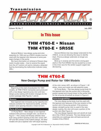
Beginning at the start of production for 1994 models, all THM 4T60-E transaxles were produced with a new-design tapered pump rotor and new-design pump casting with location changes for the suction passage (See Figures 1 and 2).

New tapered rotor increases pump capacity and reduces cavitation for improved durability, and the random vane spacing reduces a noise concern.

- (1) Pump Rotor – New design is now tapered instead of the previous straight rotor, as shown in Figure 1. The L-body and N-body vehicles were built using random spacing of the rotor vanes (340, 400 and 460) similar to the 4L60-E design. All other models will use a tapered rotor with equal spacing of the rotor vanes (400), as shown in Figure 1. All slides, rotors and vanes are still selective sizes.
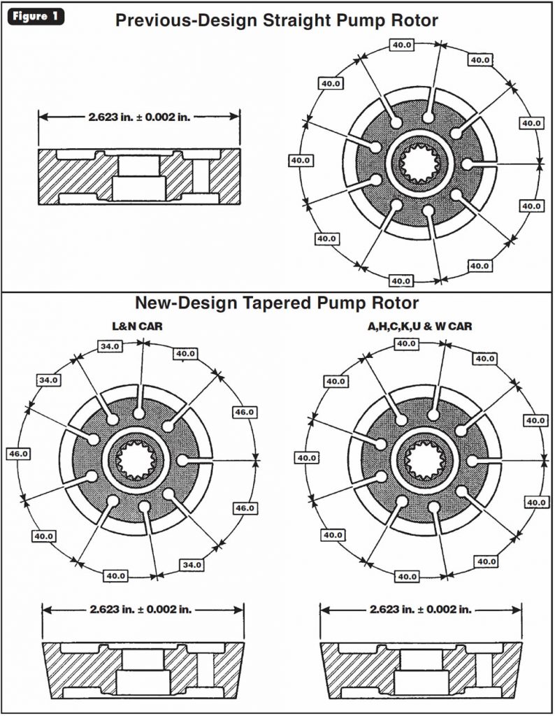
- (2) Pump Body – The new-design pump body for the tapered rotor has the suction slot in the pump pocket resized and moved closer to the center hole for the oil-pump driveshaft as shown in Figure 2.

The new-design pump body must be used with the tapered rotor because of the new location of the suction slot in the pump pocket. If the previous-design (straight) pump rotor is used in the new-design casting, the rotor will cover a portion of the suction slot (See Figure 2).
The new-design tapered rotor will retrofit all models of the 4T60-E transaxle. The new-design pump assembly as a package also will back-service all models of the 4T60-E.


The electronically controlled converter system (ECCS) control module provides two functions for the automatic-transmission control system.
Function 1:
To receive a signal from the automatic-transmission control unit (A/T control unit) with reference to Onboard Diagnostic (OBD) related items in the automatic-transmission control system. This signal is sent to the ECM when a malfunction occurs in the corresponding OBD-related part.
Function 2:
To indicate a detected fault by illuminating the malfunction indicator lamp (MIL) on the instrument panel, various sensors, switches and solenoids are used as inputting devices for this system. The MIL is illuminated in One Trip or Two Trip detection logic when a malfunction is detected by OBD in reference to A/T-related sensors, switches or solenoids.
One Trip Detection Logic:
If a malfunction is detected during the first test drive, the malfunction will be stored in the ECM memory as a diagnostic trouble code (DTC) or 1st trip freeze-frame data (available with OEM or hand-held scan tools) without illuminating the MIL. The A/T control unit does not have this memory capability.
Two Trip Detection Logic:
When a malfunction is detected on two consecutive road tests, both the DTC and the freeze-frame data are stored in the ECM memory and the MIL is illuminated to alert the driver to the malfunction.
Trouble-Code Retrieval:
Trouble codes may be retrieved using one of these two methods:
- Trouble codes may be retrieved by use of a hand-held scan tool with OBD-II capability.
- Trouble codes may be retrieved by use of the MIL in the Diagnostic Test Mode II.
Diagnostic Test Mode I:
This mode is basically a bulb-check mode for the ECM to ensure the MIL is functioning properly. If a malfunction is present, the MIL will illuminate. If the MIL will not illuminate, the bulb circuit will need to be checked.
Diagnostic Test Mode II:
With the ECM in this mode, the DTC and the 1st trip DTC are shown by the number of blinks of the MIL. The DTC and 1st trip DTC use the same code number and are displayed at the same time. If the MIL is not illuminated in Diagnostic Test Mode I, all blink codes will be 1st trip DTCs. If only one code is displayed when the MIL illuminates in Diagnostic Test Mode II, it is a DTC; if two or more codes are displayed, they may be either DTCs or 1st trip DTCs.
See Figure 3 and the accompanying text for instructions on switching the ECM diagnostic test modes and code interpretation.
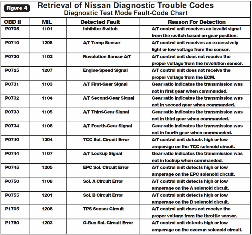
See Figure 4 for a list of DTCs and their definitions.
Switching the ECM Diagnostic Test Modes:
- Turn the ignition switch to ON (do not start the engine). The ECM should now be in Diagnostic Test Mode I-bulb check. The MIL should be illuminated.(If the MIL is not illuminated, either the bulb is bad or the circuit is shorted or open, or the ECM test-mode selector is turned to the counterclockwise position.)
- Starting the vehicle at this point will engage the ECM in Diagnostic Test Mode I. (Do not start the vehicle at this point to go on to Diagnostic Test Mode II.)
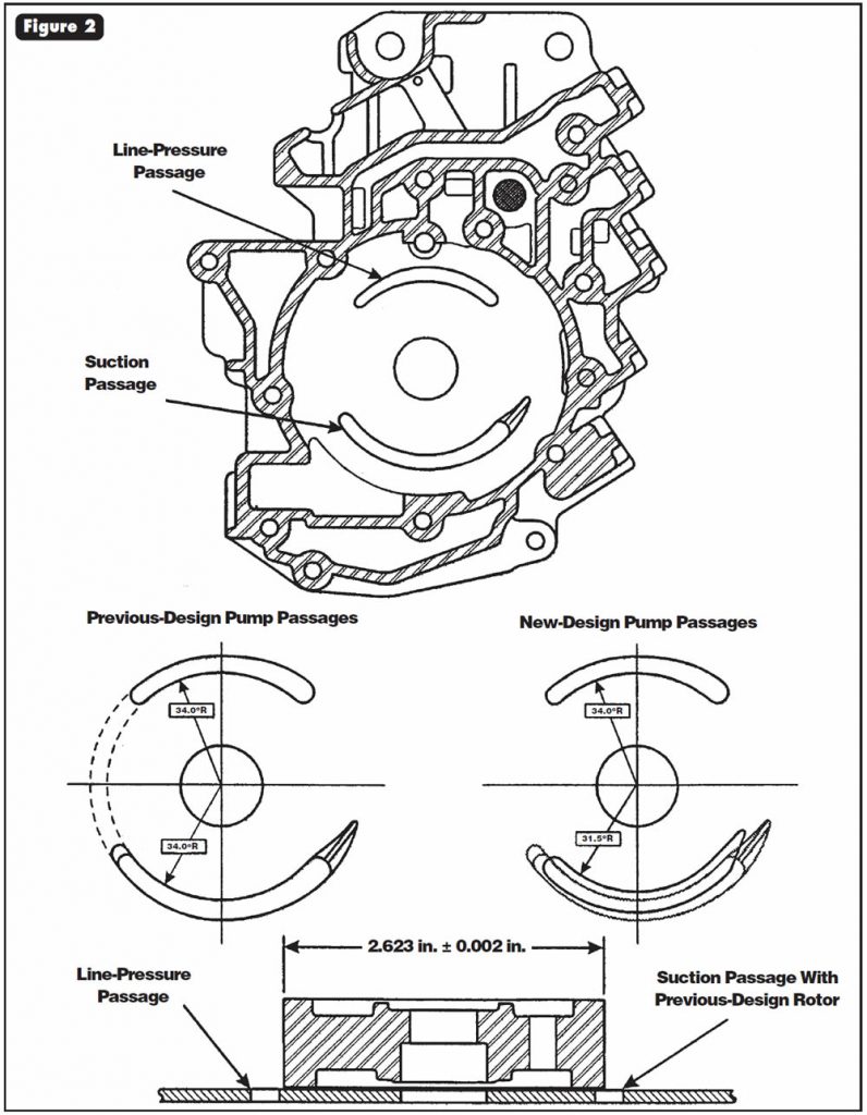
- Locate the ECM, insert a screwdriver into the hole in the right-rear corner of the control unit, and turn the mode selector fully clockwise. The MIL should go OFF. Wait at least two seconds.
- Turn the diagnostic-test-mode selector fully counter-clockwise. The ECM should now be in Diagnostic Test Mode II.
- Check the MIL for flash sequence and code retrieval. (If the selector is turned fully clock-wise again at this time, the emission-related diagnostic information that is stored in the computer will be erased from the backup memory in the ECM.)
- After code retrieval is complete and any malfunctions are corrected, turn the mode selector fully clockwise to erase codes, wait at least two seconds, turn the mode selector fully counterclockwise again and road-test the vehicle.
Note:
Switching modes is not possible with the engine running. If ignition is turned off for more than five seconds during diagnosis, the diagnosis will automatically return to Mode I. Make sure mode selector is in the fully counterclockwise position whenever driving the vehicle.
Trouble-Code Recognition:
You can identify trouble codes in Diagnostic Test Mode II by deciphering the flashes of the MIL. As shown in Figure 3, there are long flashes (0.6 seconds in duration) and short flashes (0.3 seconds in duration), with a pause of 0.9 seconds between the long and short flashes, and a pause of 2.1 seconds between codes.
The long flashes (0.6 seconds) represent the first two digits in the code, and the short flashes represent the last two digits. For example, a long flash followed by a short pause then two shorter flashes would represent code 0102. See the chart in Figure 4 for trouble codes and definitions.


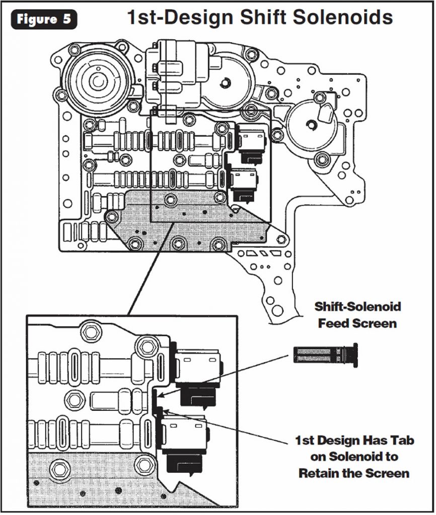
All vehicles equipped with the THM 4T80-E transaxle are now being built with new-design shift solenoids. Shift solenoid A and shift solenoid B each previously incorporated a tab to retain the shift-solenoid feed screen in the valve body, as shown in Figure 5.
The shift solenoids now are manufactured without the tabs, and an additional bracket is used to retain the screen in the valve body, as shown in Figure 6.
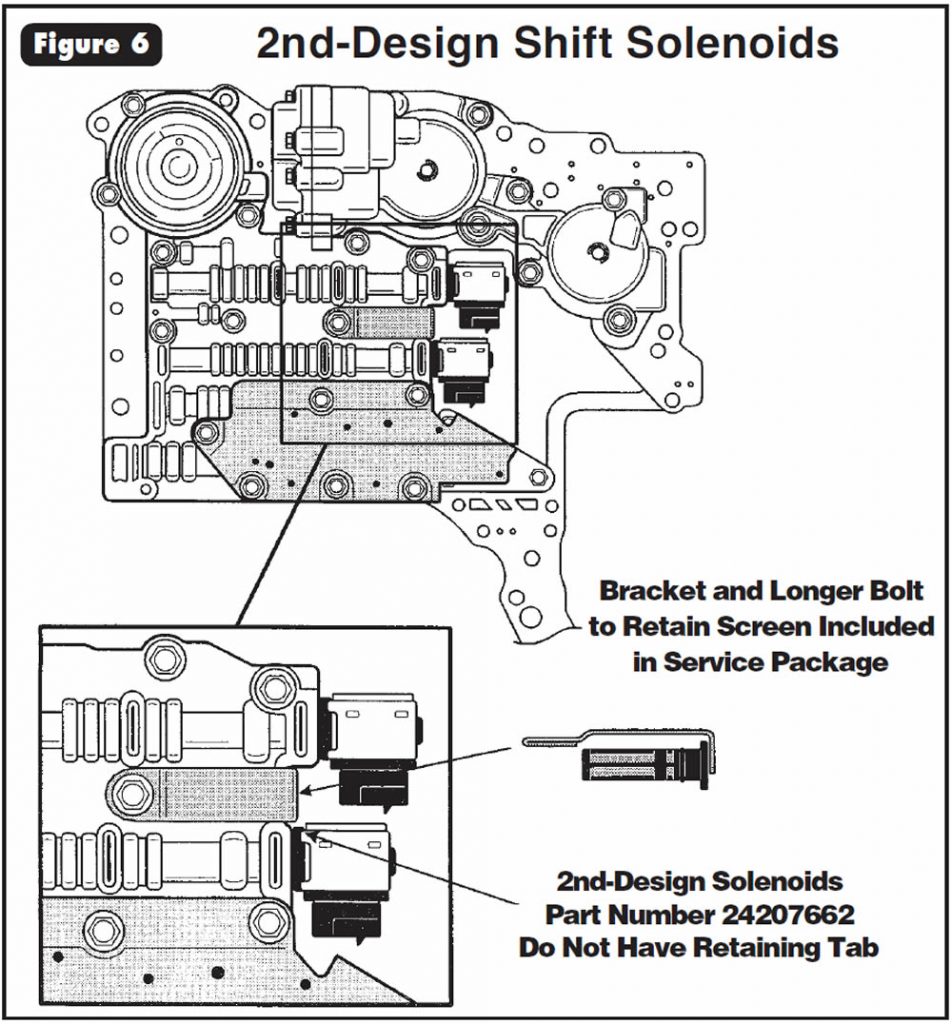
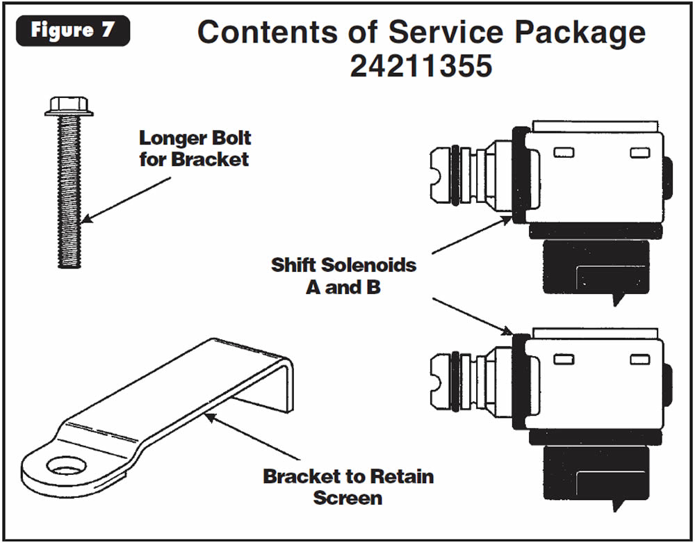
Previously General Motors has sold the shift solenoids only as part of a complete valve body. The second-design shift solenoids now are available separately from General Motors under OEM part number 24207662. Also available under OEM part number 24211355 is a service package that includes two second-design shift solenoids, a new bracket to retain the screen and a longer bolt for the new bracket, as shown in Figure 7.
Constant actuator-feed-oil pressure on the solenoid screen pushing on the tab on the first-design shift solenoids would break the solenoids’ plastic necks. The new-design shift solenoids offer greatly increased durability.
- (1) Shift Solenoids A and B – Now manufactured without the tabs, as shown in Figures 5 and 6.
- (2) Solenoid Screen Bracket – Additional bracket added to retain the shift-solenoid screen in the valve body, as shown in Figure 7.
- (3) Bracket Bolt – Longer bolt also included in service package 24211355 to accommodate the added bracket, as shown in Figure 7.
If you are servicing a vehicle with the previous-design shift solenoids that have tabs, you must buy service package 24211355, as the 1st-design solenoids are not available. If you are servicing a vehicle with the second-design solenoids, you can order just shift solenoids A and B under OEM part number 24207662.

- Shift Solenoid A (2nd Design) ………….24207662
- Shift Solenoid B (2nd Design) ………….24207662
- Service Package (to Service 1st Design Level) …24211355
- Solenoid Filter-Retaining Bracket ………………….24205848
- Bolt for Solenoid Filter-Retaining-Bracket …….8680869
- Solenoid Filter ……….8680389

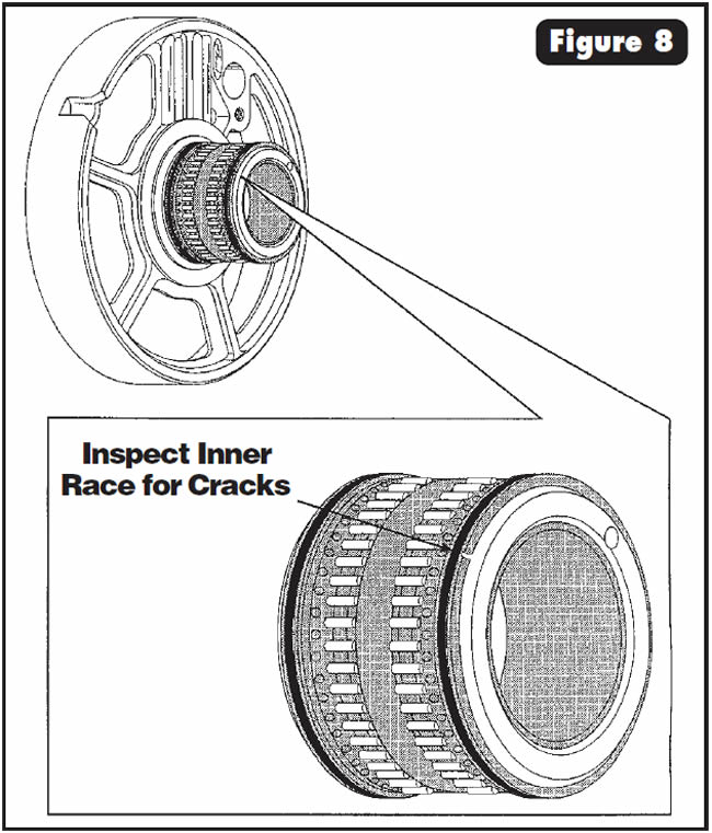
Vehicles equipped with the 5R55E transmission may exhibit a bind-up in reverse and third gears and/or wrong-gear starts.

One cause may be that the inner race for the center-support caged needle bearing has developed a crack, allowing the forward and direct clutches to be applied at the same time (See Figure 8).

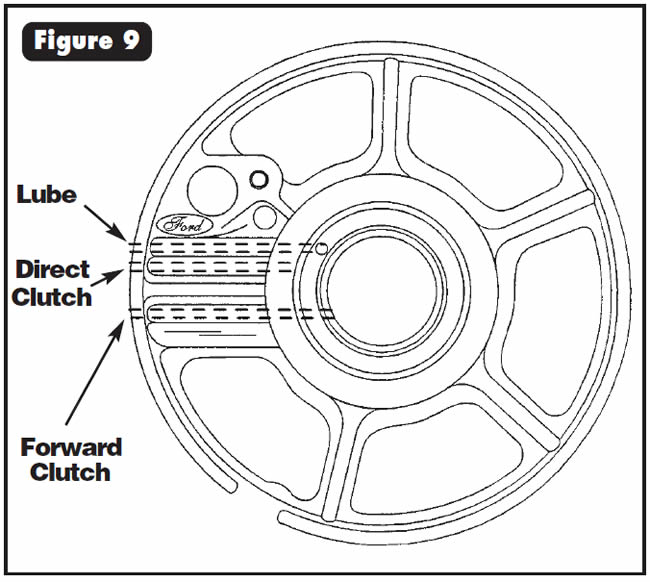
Check the forward and direct clutches with air pressure through the center support (See Figure 9), and ensure that air does not mix between the two separate circuits.
If the clutches do not pass the air check, inspect the inner race for a crack (See Figures 8 and 10). If you find a crack, replace the center support.
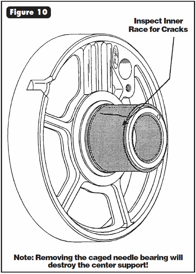
Note:
Removing the caged needle bearing will destroy the center support!
- Center Support With Bearing …..XW4Z-7A130-DA

July 2001 Issue
Volume 18, No. 7
- THM 4T60-E: New-Design Pump and Rotor for 1994 Models
- Retrieval of Nissan Diagnostic Trouble Codes: Diagnostic Test Mode
- THM 4T80-E: New-Design Shift Solenoids
- Ford 5R55E: Bind-Up in Reverse and 3rd and/or Wrong-Gear Starts


