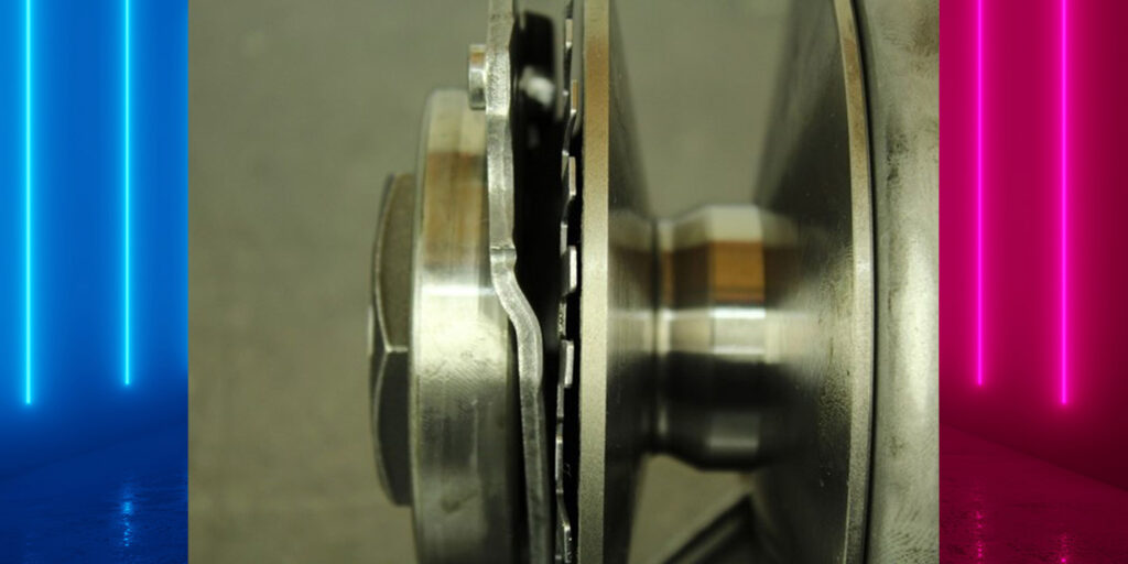
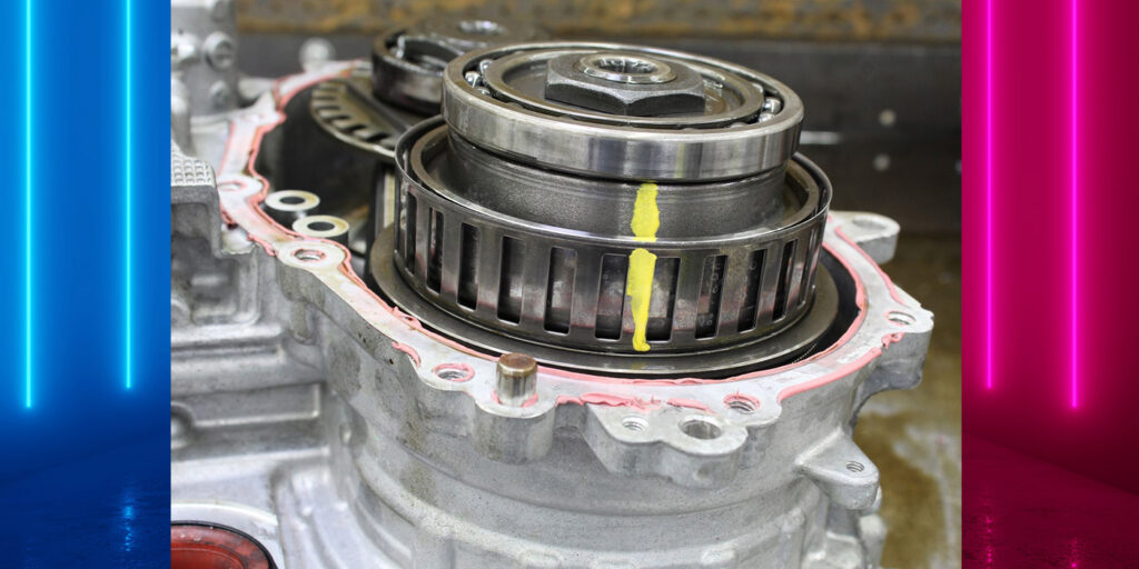
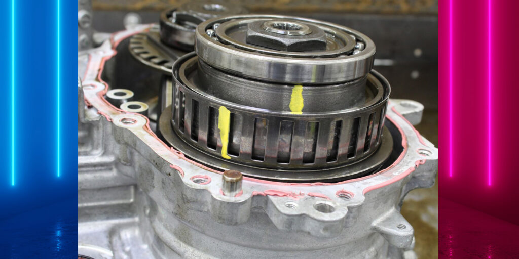
In past articles in the “Technically Speaking” series, it has been pointed out how easy it is for the primary pulley exciter ring fingers to bend while working on a JF015E continuously variable transmission (as seen in figures 1, above, and 2, below).
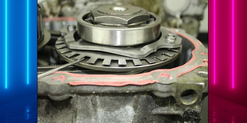
Ironically, these fingers can become bent while fixing a compromised secondary speed sensor exciter ring cage on the secondary pulley (figures 3 and 4). This too has been pointed out in past articles.
I recently encountered a vehicle that had a problem with the primary pulley signal. The car wouldn’t react to manual shifting and ratio control was all over the place. So, I attached a scope to the pulley sensors.
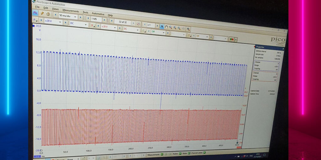
Looking at figure 5, you can see the secondary pulley speed signal in the upper blue signal on channel A. The lower graph in channel B is the primary pulley speed signal. It is supposed to look very similar to channel A. The 0-to-12-volt pulse will be tighter as the primary pulley will be spinning faster in low ratio. But as seen here, many pulses in the signal have dropped out. At first glance, the drop in signal appears to have a consistent pattern. But with a little more concentration, you can see that the drop out signal pattern is indeed erratic. If it were consistent, it would make for a great example of what bent fingers on the exciter ring would look like.
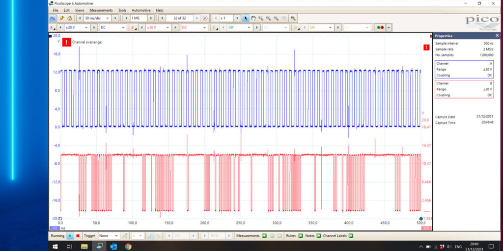
But getting back to the erratic primary pulley speed sensor signal, the computer interpreted this as a converter clutch apply malfunction and set a code for it. Additionally, line pressure went very high as a “high line pump whine” was also present.
Seeing such a clean signal on channel A for the secondary pulley speed sensor indicated that the primary pulley was not having a problem pushing the belt. This suggested to me that the erratic signal coming from the primary pulley speed sensor is being caused by a bad connection, a failed sensor or some other closely related compromise with the electrical systems integrity.
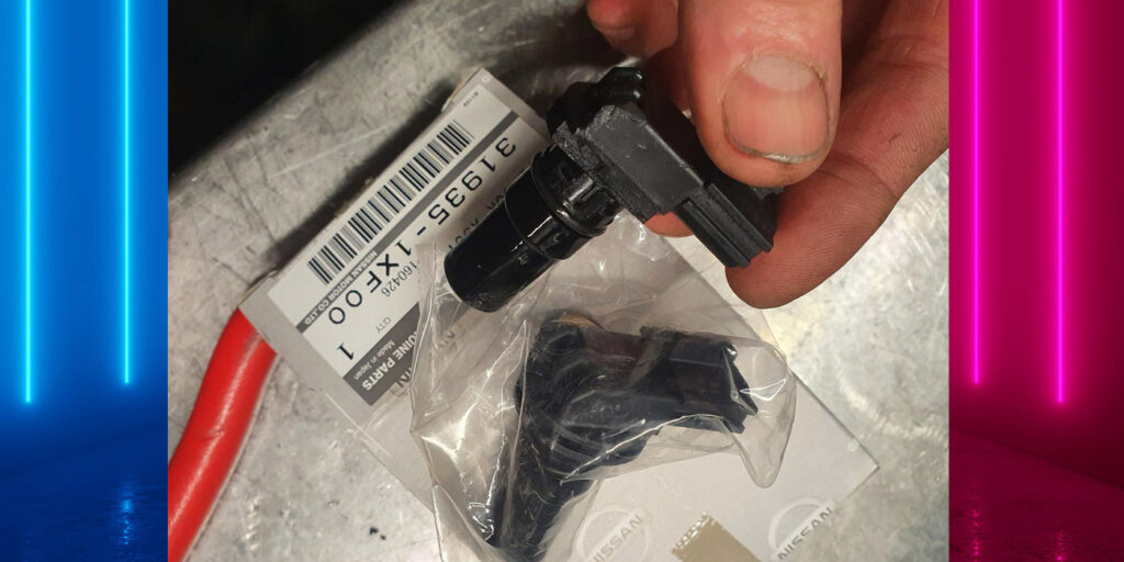
I decided to take a closer look at the sensor and discovered that part of the supporting housing was broken away (figure 6).
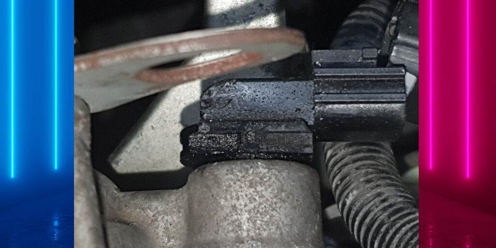
When I pressed on the sensor, a full healthy signal of the sensor returned. After replacing the sensor with a new one (figure 7), the problem was solved (figure 8). The high line pump whine went away along with setting a code for a TCC slip.
With this style CVT having a low clutch that shifts to a high clutch before the pulleys begin to ratio, a flare in the shift could now be noticed. After I performed a clutch learn to finalize the repair, it cleaned up the bad shift feel.
Michael Schmets is the European Tech Representative for ATSG.