

GM released the 6T40 in 2008 after devoting a fair amount of engineering effort to the design; however, the best laid plans of mice and men do apply occasionally. Throughout time when a transmission was developed and launched, it was almost a surefire bet that at some point changes, modifications or upgrades would occur. Some transmissions seemed to be more afflicted by this phenomenon than others, but at some point they all get tweaked.
When the 6T40 was released there was certainly no mention of GEN 1 (generation one design); however, by 2012 that term started to apply due to a substantial amount of stuff that was changed to accommodate what the OE wanted to accomplish. Not only were several items modified or upgraded, but it took an inordinate amount of time to implement. Although transmission models that fit into the GEN 2 criteria started to show up at the beginning of 2012, GEN 1 models seem to linger well into 2014 for some reason. In years gone by, major changes like this would normally be accomplished within a couple of months.
GM upgraded the 6T40 in order to improve shift quality, reduce friction losses and modify solenoid operation. One area of the 6T40 that was troublesome for GM was eliminated as part of the Gen 2 modifications, which were the TEHCM pressure switches.
Another area of the transmission got a facelift for a different reason and that was the 4-5-6 clutch assembly. The housing, piston and bonded retainer were all changed in order to control clutch balance oil more efficiently. Lastly, all of the friction plates were modified in regard to friction material and plate waviness to provide better shift quality and reduce drag during clutch release.
No sooner was the ink dry on the GEN 2 mandate than GM decided more changes were needed with the 6T40, so off to the races they went and launched –guess what – a GEN 3 version. Apparently, releasing a new version of an existing transmission with significant modifications over a stretch of time is becoming the norm due to the fact that certain applications receiving the GEN 3 upgrades started in 2014 while other vehicles continued receiving the GEN 2 stuff.
Without a scorecard it is anyone’s guess as to which team is up at bat. One application to switch over to GEN 3 was a 2014 Chevy Malibu with a transmission code of MNH. On the other hand, a 2015 Chevy Cruz might still use the previous GEN 2 version. Going forward, knowing the vehicle year, model and transmission code will not be good enough due to overlapping versions of a given transmission.
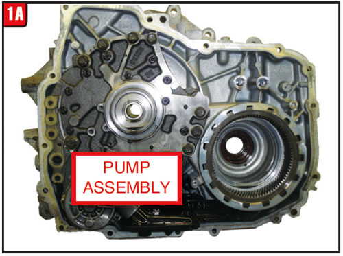
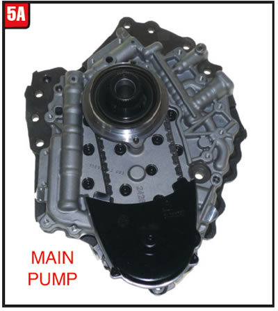
Reading the fine print is becoming a must. The upside is much of the GEN 2 transmission does carry over to a GEN 3 unit; however, a lot does not. 5A The single biggest change to the GEN 3 6T40 has to do with
the pump assembly.
GM must like the 6T70 better than the 6T40 since that is exactly the type of pump that the GEN 3 model now uses.
Bell housing/case:
To accommodate the new remote axis chain drive pump, the bell housing had to be modified big time, which affected the bell-to-pump and bell-to-case gasket surfaces (figures 1A/1B).
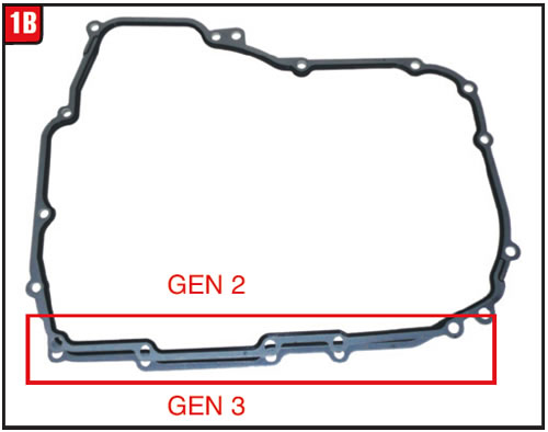
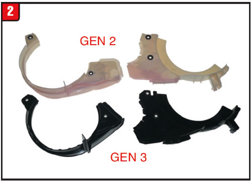
The area of the bell housing that was modified is where the pump is located and the subsequent bolt pattern. To make room for the new design pump other items were changed including the plastic oil baffles (Figure 2). In addition to the style, the material was also changed from white plastic to black.
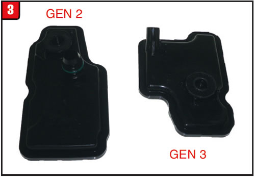
It goes without saying that a new filter had to be developed and GM decided to fasten it to the pump more like the 6T70 than the interlocking design of the previous 6T40 models (Figure 3). For some reason the individual filter is still not available separately from GM but rather part of an overhaul kit, just like previous applications.
Changes to the case were much less drastic especially in the area of the valve body. There will be calibration differences between GEN 2 and GEN 3 valve bodies, although the bonded separator plates are the same part numbers. Even though the ISS and OSS part numbers were changed for GEN 3, both sensors will retro back. The positioning of the stationary brakes and rotating clutch assembly also remained relatively untouched, which is a plus. The case contains an additional check-ball capsule.
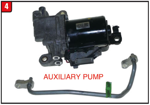
There is one aspect that will also affect bell housing and case design and that is whether the transmission is equipped with eAssist (start-stop capability) or not. If the vehicle is so equipped, there will be an auxiliary motor/pump assembly bolted to the top of the case and bell housing that has a short nipple for oil flow (Figure 4). In addition, there is a connecting tube that goes between the pump assembly and the case. Replacement seals should become available in the aftermarket shortly to reseal the assembly. The OE part number for the auxiliary pump is 24271798.
Pump assembly:
As stated, the primary difference between GEN 2 and GEN 3 transmission models is the pump assembly. In an effort to reduce engine horsepower devoted to turning an oil pump, many OE manufacturers are designing transmissions with a remote axis pump as is the case with the GEN 3 6T40. Although chain driven, the pump used in a 6T40 is completely different than one used in a 6T70 transmission (Figure 5A). It is, however, a vane type pump with a stationary slide.
The assembly consists of the pump, pump body and pump cover (Figure 5B). The aluminum pump body contains the pressure regulator valve as well as TCC regulator, blow off and lubrication regulator valves. The pump cover contains the stator support and the pump rotor shaft and bearings. Although the drive chain and sprockets look the same as the 6T70, unfortunately they are a bit smaller. Use caution not to break the locating tabs on the black plastic cover.
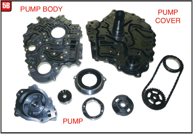
There is also a check ball between the body and cover. There are several seals and bonded gaskets attached to the pump assembly (Figure 5C). In addition to the regular torque converter metal clad seal is a small metal clad seal for the pump shaft. The large bonded separator plate goes between the body and cover and there is a bonded plate that goes between the pump and cover. There is also a molded rubber end plate that contains a locating tab. Note the position of all pump components to aid in reassembly and don’t forget the lathe cut seal that goes between the pump body and bell housing.

Final drive assembly:
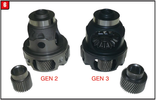
The final drive ratio has been fairly consistent with 6T40 transmissions, unlike other transmission families that had varied wildly over the years. That changed somewhat with the GEN 3 final drive ratio. A common final drive ratio for a 6T40 would be 3.87 to 1, whereas a vehicle such as a Malibu with GEN 3 will have a 3.17 ratio. There is a substantial difference in appearance as well (Figure 6). For instance, the final drive sun gear tooth count for a GEN 1 or GEN 2 is 31T; however, a GEN 3 sun gear is 41T and is substantially larger. The final drive pinion gears are also noticeably different. The splines on the outside diameter of the final drive ring gear are the same and fit all bell housings.
Center support:
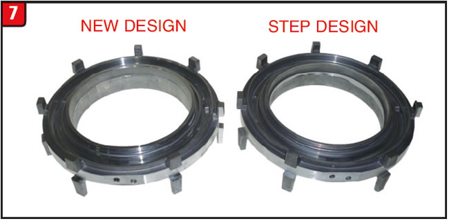
The aluminum center support used in a 6T40 has been relatively unchanged from day one. The support contains the 1-2-3-4 and L/R stationary brake bonded rubber pistons which are also common to all years. A change did occur to the support but did not affect all GEN 3 models (Figure 7). The change had to do with the basic casting around the inside edge of the bore. The previous design had a step on one side and the new design does not. The two designs will interchange and the latest OE part number is 24274885. Always ensure that both air bleeds are open.
Mechanical diode:
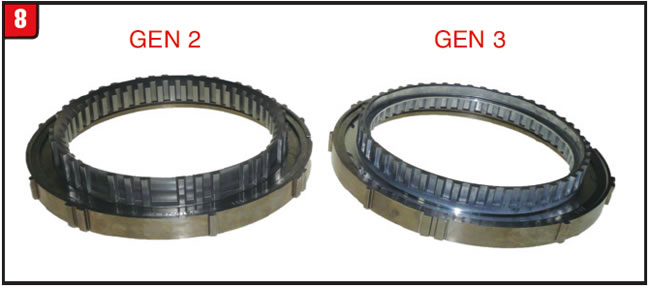
There have been several types of OWC (one-way clutches) used in transmissions from the beginning; however, the mechanical diode seems to be the current flavor of the month. The GM 6T40 has used the diode from day one without change. In an effort to cut down inertia the diode was redesigned for GEN 3 models and looks noticeably different from the previous design (Figure 8). The splined inner race material now resembles aluminum more than steel and has a step cut into the inside diameter. GM currently lists two different part numbers. The GEN 2 part number is 24274198 and the GEN 3 part number is 24274199. There is a distinct possibility that the two parts could interchange.
Friction plates:
Considering that GM just made sweeping changes to the friction plates used in the 6T40 while upgrading from GEN 1 to GEN 2 transmission models, it would be questionable that GM would do it again; however, that’s exactly what happened with the launch of GEN 3. It is virtually impossible to keep up with all the part number changes and what goes where.
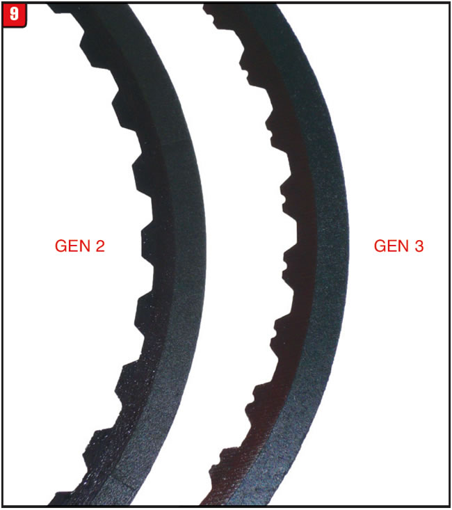
For instance, the 1-2-3-4 friction plate was changed substantially during the GEN 1 to GEN 2 upgrade in order to reduce clutch drag. The inside diameter of the friction material was increased resulting in a thinner wafer. The GEN 3 friction plate material was changed along with a different grooving pattern (Figure 9). Notches that are stamped into the teeth may also be inconsistent between production and service plates.
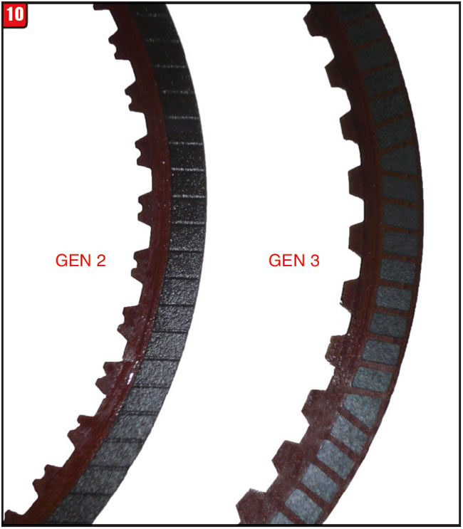
Today, it is fashionable for friction manufacturers to produce button (segmented) friction material instead of a full wafer for various reasons. Such is the case for the GEN 3 L/R friction plate. The GEN 2 plate uses a full wafer, whereas the GEN 3 is segmented (Figure 10). As with the other plates, it is questionable when notches in the teeth will appear or what could be interchanged.
The question remains, will a GEN 3 6T40 be the end of it, or will there be a new generation year after year? Only time will tell.
Special thanks to the folks at TransTec for supplying components and info in preparation for this article.


The owner of a 2007 Toyota Prius started to experience an occasional problem while trying to start the engine – as in, at times it wouldn’t. At first he thought that it was something he was doing wrong such as not placing the shifter all the way into park but then realized it was something beyond his control. When the check engine light started to dance he knew that there was a problem and decided to have it checked out. Unfortunately, he waited too long and the vehicle had to be towed into the shop.
When the vehicle arrived at the shop it started OK the first couple of times; however, it didn’t take long for it to malfunction. Once the engine failed to start at all, a code was set and the check engine light came on. Battery and powerpack voltages were checked and appeared to be OK, so the codes were cleared in order to try to start the engine again. The final attempt did not go well because instead of the engine starting as it should have, smoke started to roll out of the cover vent of the transmission.
A traditional vehicle could have many reasons why an engine would not start (turn over); however, the Toyota Prius is not a traditional vehicle. It is a hybrid and not just a passive hybrid but a full-blown hybrid, meaning that at any given time the vehicle can be propelled down the road without the assistance of a gas guzzling engine. The Prius does have a traditional engine but also has an EVT (electric variable transmission), although Toyota refers to it as a CVT.
After all of the battery, powerpack and engine possibilities were eliminated, it became apparent that the transmission was the culprit, but as to why was anyone’s guess. The next task at hand was to remove the transmission for inspection to see if in fact that the unit was bad. The first step was to pop the hood and check out the goodies, although before any wrenching took place the claws of the powerpack had to be yanked. Before working on any hybrid, always follow the procedure to disarm the high-voltage powerpack to avoid injury.
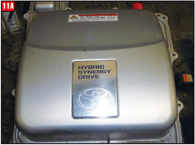
With the hood up the first image to be seen on a Toyota Prius is the inverter unit (Figure 11A). Toyota refers to the system as Hybrid Synergy Drive and the unit must be removed before pulling the transmission.
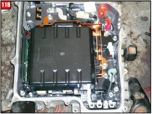
The inverter on this vehicle is rather substantial and contains a lot of electrical stuff (Figure 11B). Caution should be used when removing and handling the assembly so that nothing gets misplaced or damaged. The Ford Escape Hybrid uses a similar EVT which is also produced by the Aisin Corporation; however, the inverter is incorporated within the transmission assembly to form one complete unit, unlike the Prius.
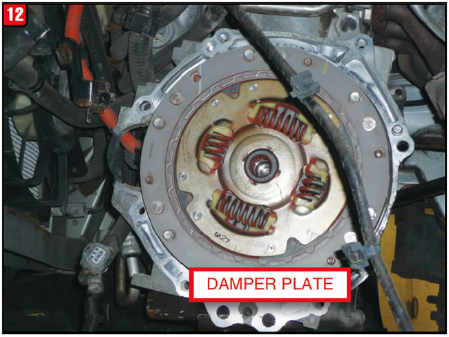
Removal of an EVT from a Toyota Prius can be a bit difficult, although there are certainly models of vehicles that are much harder to do. With the transmission removed, the back of the engine is substantially different than a Toyota equipped with a regular automatic due to not having a torque converter but rather a simple damper plate (Figure 12). The damper plate does function like any other that would be used in a manual shift or DCT application. Always inspect the damper plate for broken springs and for turbine spline wear.
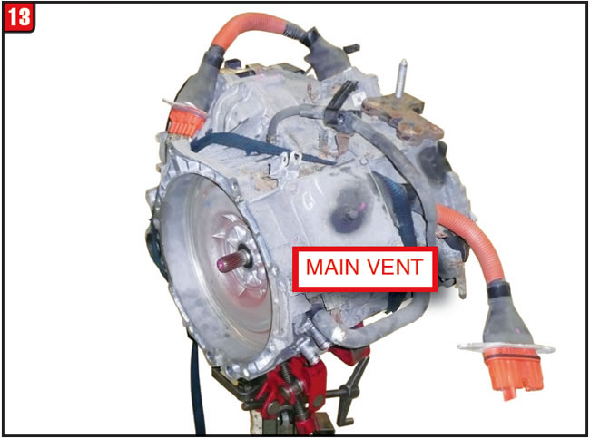
With the EVT out of the vehicle and setting on a transmission jack, it may at first glance look like a regular automatic transmission with a couple of rather large electrical cables sticking out (Figure 13). Nothing could be further from the truth. Note the stub input shaft sticking out of the bell housing and the absence of a stator support. At this point the question becomes, why was smoke billowing out of the cover vent at the precise moment that the engine would not turn over?

Although externally the Prius EVT might pass for a regular automatic transmission, the reality is that the unit has little in common with a manual shift, automatic, CVT or dual clutch transmission. The EVT basically contains two rather sizable electric motors, each of which performs specific tasks. The bell housing chunk of the transmission contains the main focus of the problem at hand, which is the MG1 (motor/generator one).
As the name implies, the front electric motor can act as a drive motor or as a generator, depending on requirements. The MG1 provides a couple of different functions while acting as a motor. One of the functions is to start the engine and another is to help propel the vehicle down the road by acting as a reactionary force for the gear set while the vehicle is being driven by the gas engine.
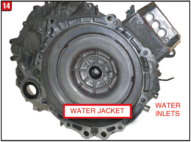
When viewed from the front of the bell housing a water jacket cover can be seen that is held in place by a large snap ring (Figure 14). The cover contains O-rings to prevent water and antifreeze from leaking out and can be a little difficult to remove. If no leaks are present, flush water through the inlet tubes to ensure good flow because the MG1 does generate a lot of heat. There is also a small tube on top of the bell housing that looks like a vent, but it’s not. There is a rubber hose that connects to the tube with a bleed valve at the end in order to bleed air out of the water system.
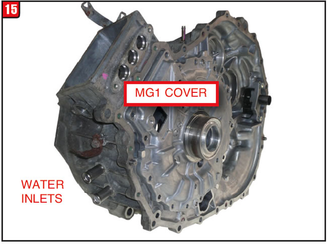
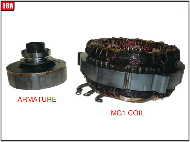
There is a large aluminum cover on the backside of the bell housing that has to be removed to gain access to the MG1 (Figure 15). The three large holes above the cover are for the MG1 power cables, which are sizable. Access to the cable bolts are under the vent cover. The bell housing also contains the bearing pockets for the main drive, transfer and differential gears, somewhat like a normal transmission.
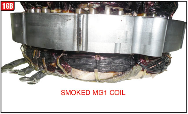
With the motor cover removed, the source of the no start condition became real apparent by sight and especially by smell because the MG1 coil windings were cooked (figures 16A & 16B). The first item to be removed was the armature, which had to be pried out, not because of seized bearings but because of how powerful the magnet is. Use caution when handling any EVT armature to avoid getting fingers pinched or causing electrical interference to other components. With the armature removed, the coil can be unbolted and removed from the bell housing.
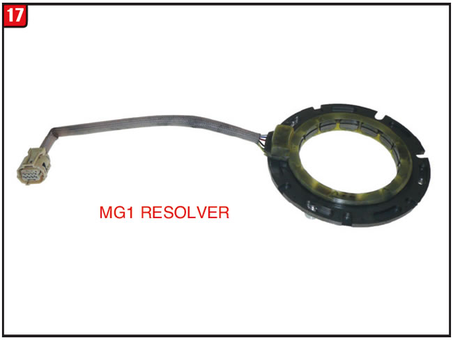
The motor cover also has one item that bolts to it, which is the resolver (revolution sensor). The resolver has a harness that plugs into a case connector (Figure 17). Before removing the three resolver bolts from the cover, mark the position of the resolver so that is it is returned to the exact position.
There is one component in the EVT that does exist in a normal automatic transmission, which is a planetary gear set. The planet set is needed in order for the engine to propel the vehicle as well as the electric motors. The assembly consists of the planet carrier and input shaft, a sun gear, ring gear and hub along with the driving shell that is made to a sprocket (Figure 18). The sprocket is for a drive chain that is used in this model of EVT.
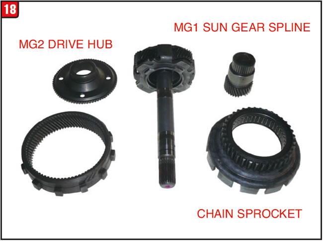
Basically, the ICE turns the input shaft that drives the planetary carrier and ultimately the ring gear and chain sprocket. The sun gear, which is splined to the MG1, rotates at various speeds to enable the planet set to work while in engine mode. Alternatively, the ring gear hub is splined to and can be driven by the MG2 individually or in conjunction with the ICE, a fairly simple design.
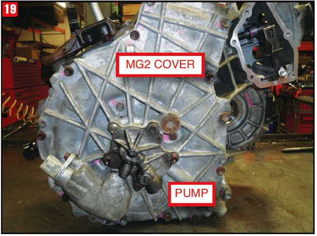
The MG2 is housed within the main case section and is accessible by removing an external end cover (Figure 19). Bolted to the end cover is a much smaller plate which happens to be a pump cover. The pump gears used for this transmission are about the size of a 50-cent piece because the only requirement of the pump is to provide lubrication. As in the case of the MG1 cover there are three bolts toward the center of the MG2 cover that attach to the resolver, which should not be removed until later if needed.
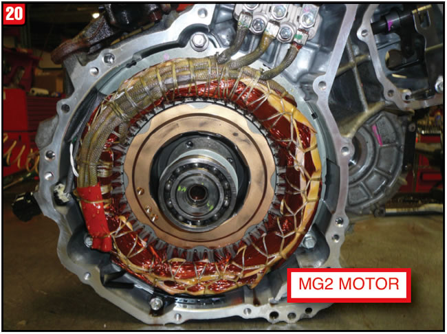
With the end cover out of the way, the MG2 can be removed in the same manner as the MG1. The main difference is that the MG2 is noticeably larger (Figure 20). That means more weight and a lot more magnetic pull, so be careful when handling.

For this type of failure there are a couple of repair options. Fortunately, there was an inexpensive core available that happened to have a good MG1 so that’s what was used. Another option can be to have the motor rewound, although that can be fairly expensive. Although Toyota does not provide the individual motor assemblies, they do provide the housings that contain the motors. List price for the bell housing that contains the MG1 is approximately $1,000, whereas the main case section and MG2 list for approximately $1,400. Other internal components are available separately from Toyota. Always specify the year due to model changes. This particular transmission was a P112.
Although Toyota Prius transmissions seemed to hold up pretty well, there are now a lot of them in this country racking up a lot of miles and at some point can fail, so break out the multi meter.


January 2017 Issue
Volume 34, No. 1
- GM 6T40 Generation 3 modifications
- Toyota Prius No-Start Condition


