


The owner of a 2005 Nissan Maxima arrived at the shop after being referred by a general-repair facility. Apparently, the other shop had tried to address the customerʼs complaint, but with little success. Trying to separate an initial problem from any subsequent shop-induced problems can, at times, be difficult, so careful review of the facts was important. The Maxima was equipped with a 3.5L engine and 5-speed automatic transmission with only 93,000 miles on it.
The vehicle was taken to the first shop with a complaint of harsh engagement (garage shifts) and erratic shifting. In addition, the check-engine light would come on at times, and using a scanner the trouble code P0726 was pulled. Code P0726 was understood by the shop to be an input rpm sensor code. The normal procedures were performed to try to isolate where the problem was, such as checking the wiring harness and connectors as well as replacing the transmission ISS. After a fair amount of time invested, the manager of the shop decided to cut his losses and move on: Enter shop No. 2.

After retracing the steps of the first shop, a scanner was connected to the Maxima to see if anything else was going on beyond what was originally stated. With the check-engine light on, the transmission had a harsh neutral-to-drive apply and 3rd-gear start (fail-safe). Once the code was cleared, everything returned to normal, at least for a short time. Once the check-engine light returned, the transmission-engagement problems did as well.
When the technician went online to review the P0726 code definition, everything became clear. What the people at the first shop missed was the wording of the P0726 code, which actually stated “Engine speed input circuit performance.” Apparently, based upon the wording of the DTC description and the fact that most automatic-transmission trouble codes are in the 700 series, the technician at the time chose to go after the transmission ISS.
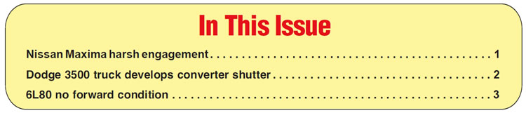
After digging a little deeper, the item that was causing all of the issues ended up being the camshaft position sensor (CMP). The camshaft position sensor was for bank No. 2 and was located at the driverʼs side of the front cylinder head. The sensor is a basic Hall Effect design and is held in place with one bolt (Figure 1).

When the technician at the first shop was using a scanner to determine the trouble code that was causing the check engine light, he had it set to illustrate transmission trouble codes. Although the P0726 code did display in this mode, it was somewhat deceiving due to the fact that the code is actually engine related. Had the technician switched the scanner from transmission mode to engine mode, additional information would have been available.
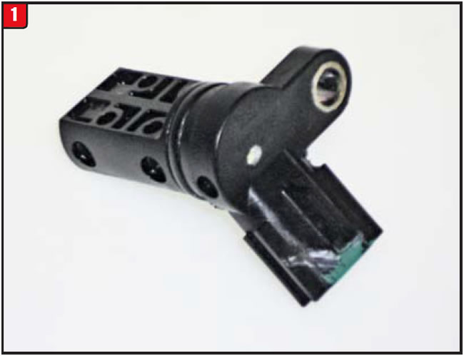
With the scanner in engine mode, an additional trouble code popped up, P0345. The code actually refers to a camshaft-position-sensor issue. The Nissan Maxima has not one but two different camshaft position sensors. A trouble code number P0340 denotes a camshaft-sensor issue for the engine bank No. 1. The trouble code number P0345 denotes a camshaft-sensor issue for the engine bank No. 2, which helps to isolate which sensor to address. There is a slight difference in how the sensors function; however, they cannot physically be interchanged. The electrical schematics are also slightly different and are marked accordingly, (Figure 2). The illustration in Figure 2 is for the sensor that monitors the second bank, which happens to be the cylinder head that is forward toward the radiator.
Beyond the transmission-related issues was another problem that should have been a tipoff, which was starting the engine. At times, the engine had to crank over several revolutions before it would start, while at other times the engine would fire almost immediately.
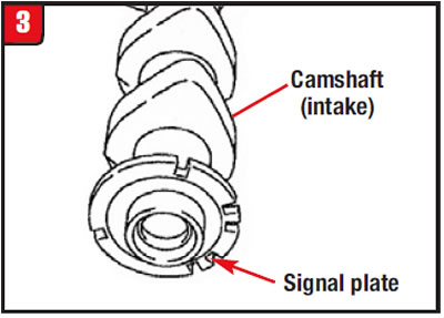
As with other sensor-related problems, itʼs not always the sensor. A bad wiring harness or electrical connector can certainly create similar conditions, and in the case of the Maxima, the camshaft itself could be the problem. Metal buildup or chipping at the camshaft signal plate can cause problems as well (Figure 3). With the camshaft sensor removed and using a flashlight, closely inspect the signal plate for any irregularities.
Accessing trouble codes is necessary to determine the cause of any problem; however, with all the modules on vehicles today it is equally important to monitor all scanner modes to leave no stone unturned.


A customer who was somewhat of a do it yourselfer brought in his 2010 Dodge 3500 monster truck due to a transmission issue. The vehicle was equipped with a ground pounder 6.7L diesel engine and a 68RFE transmission and was 4WD for added measure. It had 73,000 miles on it and of course was loaded with diesel performance enhancement gadgets.
According to the customer, when the truck started to act up he jumped online to see what could be done to address the problem, and based upon what he read, he decided to replace the valve body assembly. He purchased a reman valve body from the local Dodge dealer, installed it and supposedly performed a reflash; however, after the smoke cleared the initial problem was still there. The reason that the valve body didnʼt work was because the damage was a bit more extensive; specifically the underdrive clutch was smoked, which was causing the erratic shifting and slippage.
The repair seemed like a no-brainer; therefore, the shop completely rebuilt and reinstalled the transmission along with a reman torque converter. All the basics were performed, such as flushing cooler lines, adding the correct transmission fluid and doing a routine computer relearn. The vehicle was road tested and everything seemed to work well, that is until the customer returned two days later with what appeared to be a converter shutter.
The converter shutter was somewhat uncommon in the way that it occurred. On takeoff and depending on the amount of throttle given, the torque converter would lockup at the right time and had a nice firm apply. The issue was between 45 and 55 mph. A shutter would occur by leaning on the throttle a little heavy; however, it felt more like a driveline vibration, as if the driveshaft was out the balance. All other transmission functions were fine, so the question became what to do next.
Before turning a wrench, the technician needed to determine which component was at fault, such as the valve body, solenoid block, pump or torque converter. Although any of these items could conceivably cause a converter problem, the technician reviewed basic information including oil diagrams and electrical schematics to see which one was most likely to be suspect. To make matters worse, no diagnostic trouble codes were set that could have helped minimize the process.
After careful review, it was decided that the torque converter was the most likely candidate. The valve body after all was a reman from Chrysler and was inspected again during the rebuild.
From a physical testing standpoint there is not a lot available for a later-model 68RFE transmission or from a scanner standpoint with a 2010 Dodge 3500 diesel. The scanner used on this truck did provide some helpful information such as torque converter rpm slip.
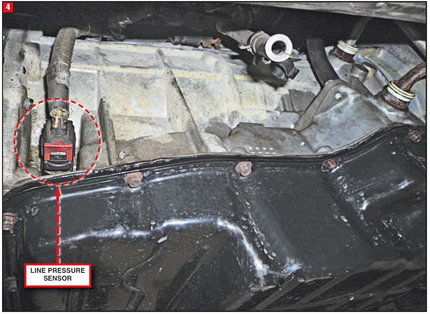
On the transmission side, the first test that needed to be performed was a line pressure test. Unlike other transmissions that use a simple threaded test plug, the 68RFE is a bit more involved. The line-pressure access port is on the right (passenger) side of the transmission case (Figure 4). To gain access to line pressure requires removal of the line-pressure sensor and harness connector.
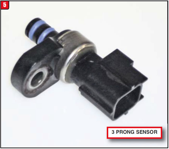
The line-pressure sensor used on the 45RFE/68RFE family of transmissions is a pressure transducer, which is held into the case by a bolt. To prevent potential leaks the sensor has two O-rings just for good measure (Figure 5). The line-pressure sensor provides continuous feedback to the computer as to pressure levels, so that the computer can send the correct signal to the line pressure solenoid.
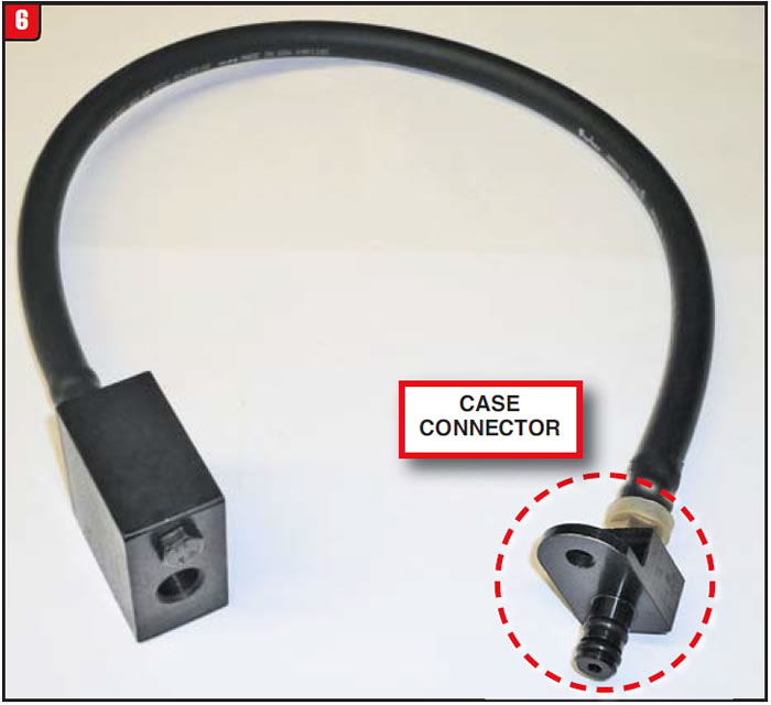
To properly test transmission line pressure requires a special adapter, which fits into the case just like the line pressure sensor. The Chrysler (Miller) tool part number is 8259 and is available from local dealers or from various tool suppliers. Not only does the adapter fit into the case like the sensor, the sensor itself plugs into the adapter along with a regular pressure gauge (Figure 6). This arrangement not only provides traditional pressure testing but will also enable the use of a scanner to compare sensor output to actual pressure readings. Note: the adapter shown in Figure 3 differs from the previous adapter design, which was a rigid type. The new design adapter uses a flexible hose to make the hookup much easier. Overall, line-pressure and sensor-feedback signals were right on target.
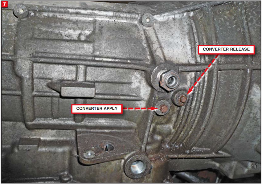
The next area of concern was actual torque converter apply pressure. Certain types of automatic transmissions have converter pressure taps, whereas others do not. When the 45RFE family of transmissions was released in 1999, there were actually two pressure taps on the right side of the case, one for apply and one for release (Figure 7).
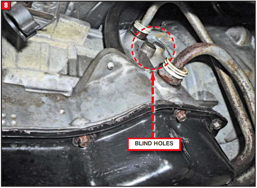
Unfortunately, by the time the 2010 Dodge truck was released, Chrysler apparently decided that the converter-pressure taps were unnecessary and quit installing them at the factory (Figure 8). In this case, having the converter-pressure taps would have been of great benefit due to accessing the apply pressure. It would be advisable that during the rebuild process of later a model unit that apply and release ports be drilled and tapped.
Due to previous wear issues with RFE-style pumps, all valves and valve bores were vacuum checked in the pump to ensure excessive leakage was not present. Based on the inspection, the pump was ruled out as a possible problem, as was the valve body/solenoid block, which left the converter as the target.
After another torque converter was installed, the vehicle was driven and worked well without any shutter condition. The converter was cut open to see what was causing the issue, but internally everything looked good with no sign of slippage, making it a Ripleyʼs believe it or not scenario. Apparently, the converter just did not like this particular truck.
Most lockup systems have a release mode, partial apply mode and full apply mode. The Dodge truck in this case has a forth mode referred to as a gradual release mode, which supposedly softens the transition from full lockup to release of the piston during a higher speed, heavier throttle condition. Although the converter lining was sufficient during lockup of the converter, apparently it was not during the gradual release phase. Sometimes an extra tweak is needed. The question is when.


The owner of a 2010 Chevy Silverado contacted the shop and stated that his truck quit moving suddenly. He also stated that, at times, something just didnʼt feel right while shifting the transmission from park to drive and that the issue had been occurring for some time. Based upon the fact that the truck didnʼt move, the owner agreed to have it towed in so that an inspection could be done.
Once the truck arrived, the preliminary information was gathered and a basic inspection was performed. The vehicle was equipped with a 6.0L engine and a 6L80 six-speed transmission and had 83,000 miles on.
The truck was 2WD and the engine seemed to run well. The customer indicated the truck had no movement – going forward that is. However, reverse was right on the money, which meant that at least the pump was intact.
A scanner was hooked up to check for any trouble codes and there was one, a P1700. The pan was dropped to look for internal damage, but it was relatively clean and the fluid was in fairly good condition. The decision was made to pull the unit and peel it down to look for internal damage. Once the transmission was disassembled, the reason for the no forward movement condition became obvious. The 1-2-3-4 (forward) clutch cushion spring had broken, preventing apply of the clutch assembly. The rest of the transmission was in relatively good shape; therefore, it was rebuilt with the normal stuff.
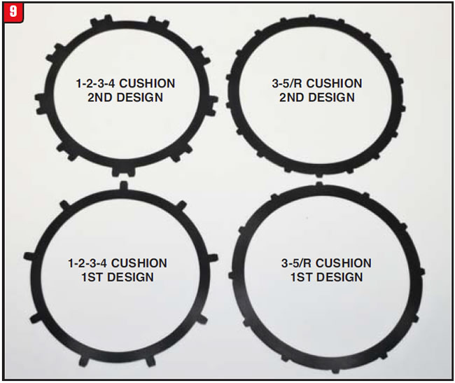
The only items beyond the basics that were replaced were two cushion springs, one for the 1-2-3-4 clutch pack, which was broken, and the other spring for the 3-5/R clutch pack. Apparently, there have been durability issues with both springs resulting in updated designs (Figure 9). The 1-2-3-4 cushion spring has been updated from a 9-tang to an 18-tang design with a new part number of 24239615. The 3-5/R cushion spring has been updated from a 12-tang to an 18-tang design with a new part number of 24239828. A good practice would be to change any of the old designs automatically.
After rebuilding the transmission, it was reinstalled and taken for a road check. Initially, the unit worked well; however, as it warmed up things started to change and not for the better. Forward apply got worse the longer the vehicle was driven, to the point that even the upshifts were affected. After the simple options were eliminated, the transmission was removed for the second time and partially disassembled in order to find out what went south.
Due to the fact that forward engagement was the issue, the focus turned to the 1-2-3-4 clutch assembly, which is situated in the 3-5/R combination clutch drum. Although the initial problem was no forward engagement caused by a broken cushion spring, the current issue was not as finite. Since forward apply would get worse as the transmission warmed up, special attention was paid to items like seals, sealing rings, the apply piston and housing. As luck would have it, the apply piston for the 1-2-3-4 clutch pack had a hairline crack that was missed by the rebuilder. Like other components in various transmissions that have had hairline cracks, the 6L80 clutch assembly air checked well and the builder did not notice any excessive leakage. Unfortunately, that was not the case once the vehicle was on the road.
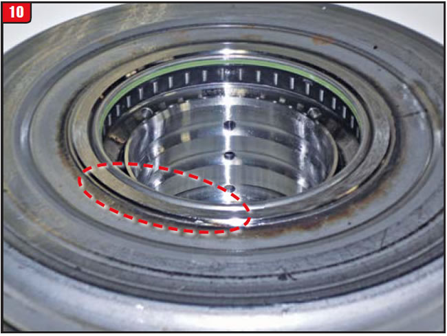
Normally, the fix would be to replace the damaged part; however, the 6L80 issues go beyond just the apply piston. There have been other problems with the overall clutch assembly. The clutch drum directly behind the pump is a dual-purpose assembly. The drum houses both the 1-2-3-4 and 3-5/R clutch assemblies that are applied just as the names indicate. The drum itself is a stamped steel design that has a welded center tower, which has been known to crack (Figure 10). In addition, there have been instances where the clutch pack snap ring can blow out.
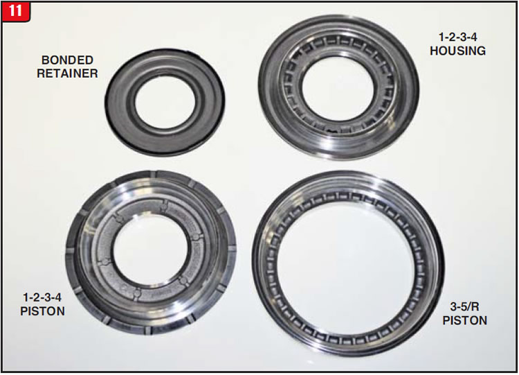
Beyond the housing problem 11 and cushion-spring failures is the issue of cracked pistons, not only the forward apply and housing, but the 3-5/R piston as well. As with any components that have had a tendency to fail, all of these items have been improved over the years. The question is, should one item or all items be replaced? The updated 1-2-3-4 apply piston is part No. 24238700 and is sold separately. If needed, the forward piston housing is also available separately under part No. 24262679 and is aluminum just like the piston. The third part in the equation is the 3-5/R piston and is part number 24242871.
The 1-2-3-4 is the first piston in the stack up and has the pocket for the bonded retainer (Figure 11). Use caution when purchasing used parts to ensure that 6L80 and 6L90 components are not mixed.
The drum itself can be purchased separately under part No. 24263590; however, it is completely stripped, with no other stuff. Based upon the various component upgrades, the best option would be to purchase the loaded drum version under part No. 24259848 (Figure 12). The loaded drum assembly for a 6L90 is part No. 24259850.
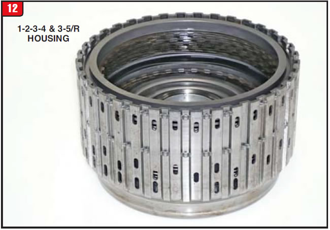
By purchasing the loaded-drum assembly, all previous issues are handled in one stroke, which in the case of the Silverado could have certainly saved a lot of time and effort.

January 2016 Issue
Volume 33, No. 1
- Nissan Maxima harsh engagement
- Dodge 3500 truck develops converter shutter
- 6L80 no forward condition


