
Issue Summary:
- A break or short in wiring or possible failure of the tow/haul mode switch can cause tow/haul mode to be inactive and may set code B2722.
- Loss of AFL-valve pressure can result in a neutral condition either during or immediately after the shift to fourth gear in a 4L80-E.
- A Saturn Vue with the AF33-5 transmission in limp mode with code P0717 set may have a faulty input-speed sensor.


Tow/haul mode is inactive. The light on the dash will not illuminate when the switch is activated on the shifter handle. This condition could cause code B2722 to set. In some diagnostic information, the tow/haul mode switch is referred to as a “preference switch.”

A break or short in wiring in the area where the shifter arm pivots on the steering column; possible failure of the tow/haul mode switch.

Repair the wiring or replace the switch. The switch and wiring are an integral part of the shift lever; it comes as an entire assembly.
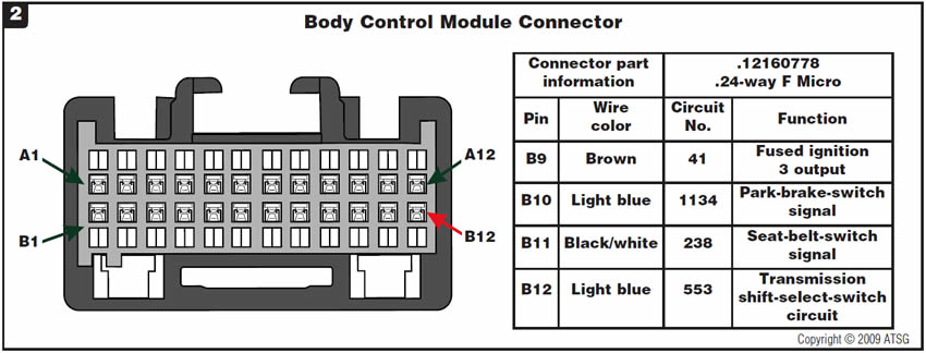
When you’re trying to find a wire schematic either in engine performance or transmissions, there is none to be found whether you’re looking in a factory manual, ALLDATA or Mitchell OnDemand. The wire diagrams are in the body-control-module schematics only (Figure 1).
To test the function of the tow/haul switch on a 1999 Chevrolet Silverado 1500 at the body control module, check for voltage on the light-blue wire at pin B12 on the BCM. Do not confuse this wire with the light-blue park-brake-switch signal wire on pin B10. Use the connector view in Figure 2 to determine the correct connector-pin number. With the key on, engine off, 12 volts should be present at terminal B12. If no voltage is present, check for a short to ground in the area of the steering column where the shifter arm pivots.
If voltage is present, toggle the tow/haul switch to see whether the voltage drops to zero and back to 12 volts; this will verify the integrity of the switch. If the voltage doesn’t change, either there is a break in the wiring to the switch or the switch itself may be bad. At this point you can short the light-blue wire at pin B12 to ground to verify that the tow/haul light in the dash is working correctly.
Check the tow/haul parameter on the scan tool for a state of change as the switch is cycled; the scan-tool-parameter change of state should match the DVOM display.

- Tow/haul switch & shift-lever assembly (sold as one assembly). . . . . . . . . . . . . . . . 26075107


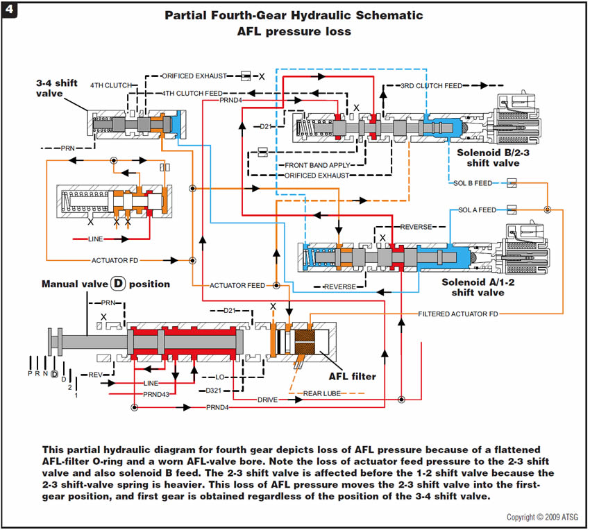
Before or after overhaul, a GM vehicle equipped with the 4L80-E transmission exhibits a complaint of a neutral condition either during the shift to fourth gear or immediately after the shift.
One cause may be a loss of actuator-feed-limit (AFL) valve oil pressure in the valve body, or a leak in the shift solenoid B circuit.
The AFL valve is used to control the amount of solenoid pressure that is fed to shift solenoids A and B and the force-motor/EPC solenoid. If AFL pressure is inadequate, the solenoids cannot function properly. AFL pressure can be lost because of a worn bore in the AFL-valve lineup, or a damaged or worn O-ring on the AFL-valve filter in the valve body behind the manual valve.
A pressure leak in the AFL circuit can lead to reduced pressure at the 2-3 shift valve. If this occurs, the 2-3 shift-valve spring may push the valve back into the first-gear position. This causes the transmission to immediately make a shift back to first gear, which feels like neutral because first gear is in an over-speed condition. The reason an issue with the 2-3 shift valve occurs before a problem with the 1-2 shift valve is because the shift-valve spring is heavier on the 2-3 shift valve, causing the valve to return more easily to its resting position.
Additionally, a leak in the circuit for shift solenoid B can create the same condition. The transmission can make a shift back into first gear during or immediately after an upshift into fourth. A loss of shift solenoid B oil pressure can be caused by a defective solenoid, a leaking solenoid O-ring or an inadequately sized solenoid feed hole in the separator plate.
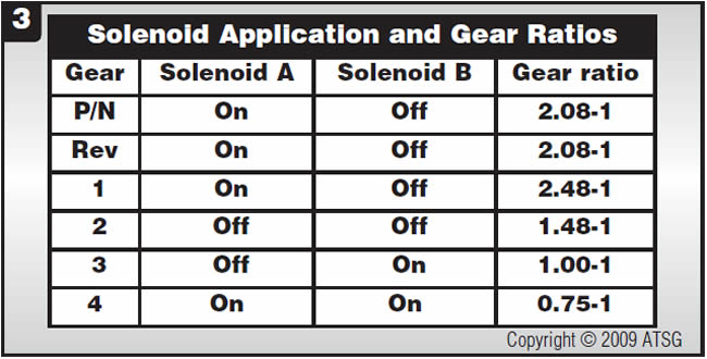
A scan tool may help the technician diagnose this problem by monitoring the parameters for gear ratio during the upshift into fourth gear. Fourth-gear ratio for the 4L80-E is 0.75-1; first-gear ratio is 2.48-1. A ratio of 2.48-1 on the scan tool when the shift takes place would indicate that the transmission has shifted back to first gear. The chart in Figure 3 shows gear ratios and shift-solenoid application.
Refer to Figure 4 for a partial hydraulic schematic of the circuits for the AFL valve, 2-3 shift valve and shift solenoid B.
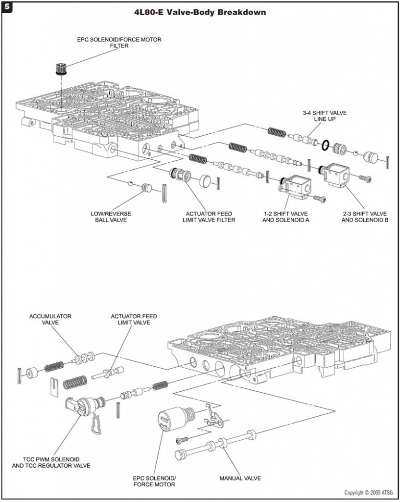
Check the AFL bore in the valve body and inspect the O-ring on the AFL filter. Replace the O-ring if it is damaged. If the AFL bore is worn, a boring tool and a sleeve and valve kit are available from Sonnax, along with a shift-valve-spring replacement kit for both the 1-2 and 2-3 shift valves. Refer to Figure 5 for a valve-body breakdown showing listed components.
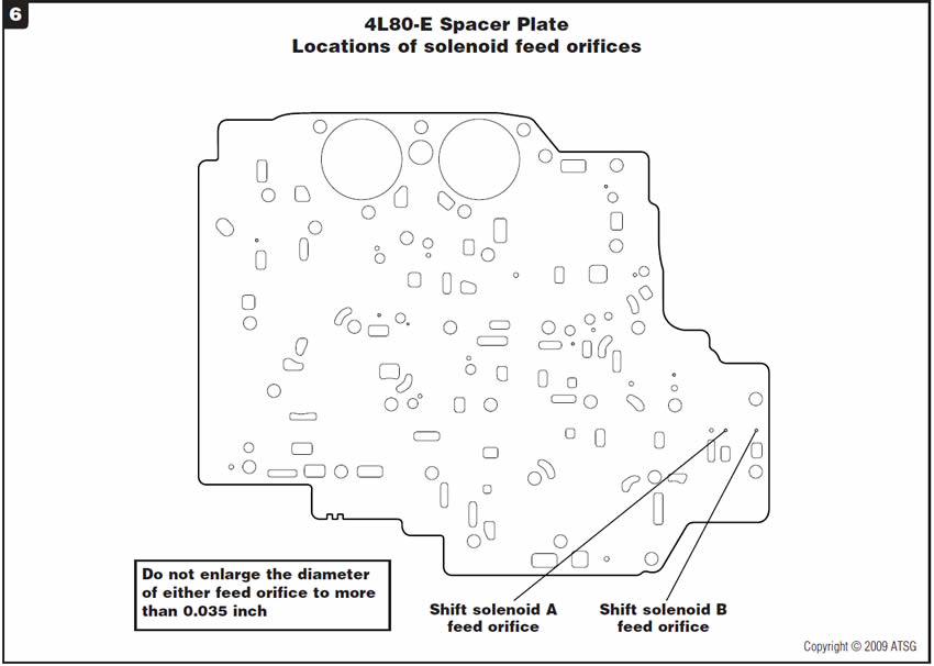
If the AFL valve and the filter are in good condition, it may be necessary to replace shift solenoid B. In addition, the solenoid feed hole in the separator plate can be enlarged slightly to overcome this condition. Using a 0.035-inch drill bit, carefully enlarge the solenoid feed hole. Do not enlarge the solenoid feed hole to more than 0.035 inch. Refer to Figure 6 for the location of the shift solenoid B feed hole in the separator plate.


The vehicle comes to the shop in limp mode with code P0717 set for “Input Speed Sensor Signal Low.”
The input-speed sensor, like the output-speed sensor, is a two-wire Hall-effect sensor. Both sensors are supplied system voltage on the “ISS/OSS HI” circuit and then produce a toggled voltage signal on the
“ISS/OSS LO” circuit, as seen in the electrical schematic in Figure 7.
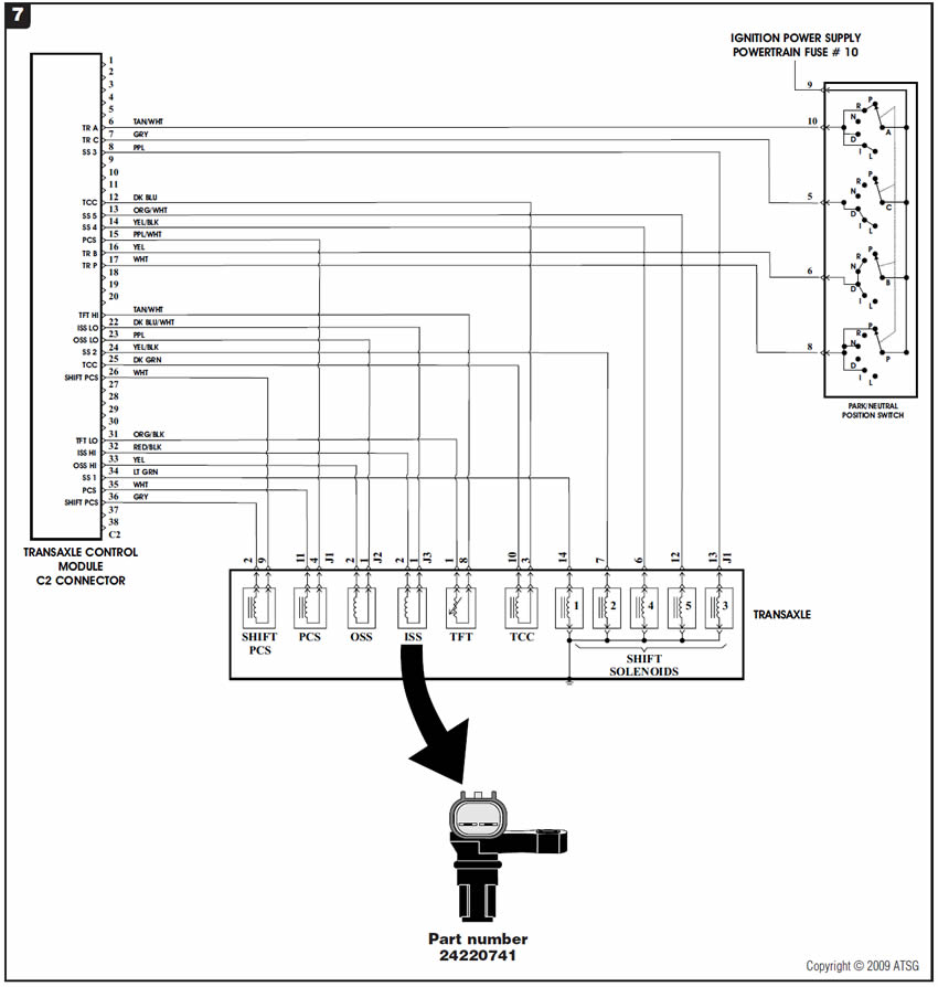
Figure 8 shows the TCM connector and terminal assignments. The voltage signal is unique in that the low end of the signal is 0.6 volt and its high end is 1.6 volts. This means that the actual switched voltage is one volt.

For those who have the AF33-5 GM technician guide, the explanation of the ISS operation is extremely confusing, because the guide says “the sensor is supplied a reference voltage of 0.6 volts. It also stipulates that the size of the output voltage does not depend on a rotation number and is fixed at 1.4 volts.” This is misleading at best.
The scan tool displayed an engine speed of 776 rpm, but the ISS parameter was zero. With the ignition on, engine off, the voltmeter indicated that the ISS signal wire had 7.6 volts on it and the OSS signal wire had 1.6 volts. This could only mean that the ISS signal wire was shorted to power or the sensor was bad. The ISS was unplugged and checked for voltage, and there was none; this led to the diagnosis of a faulty ISS.
Once the ISS was replaced, the signal readings were normal; the ISS and engine-speed readings were close to each other.
- Input-speed sensor. . . . . . . . . . . . . . . . . . . 24220741

January 2009 Issue
Volume 26, No. 1
- GM Tow/Haul Mode: Malfunction of tow/haul switch
- General Motors 4L80-E: Neutrals during or after upshift to fourth gear
- Saturn Vue with AF33-5: Vehicle in limp mode; code P0717 set


