

The M6HA and BAXA family originated in the 1997 Honda Prelude and the 1998 model Honda Accord. Other members of this family include MAXA, B7XA, MDWA, B7TA, B7YA, M7ZA, B6VA and M7WA.
Although the designations and configurations for these transaxles are different, the shift strategy and clutch-pack applications are exactly the same. The clutch-pack applications for these transmissions are:
• The 1st clutch is on in 1st gear
• The 2nd clutch is on in 2nd gear
• The 3rd clutch is on in 3rd gear
• The 4th clutch is on in 4th gear.
This family of transaxles uses clutch-to-clutch gear-change strategy. This requires precise shift timing on behalf of the powertrain control module to control the amount of overlap on each gear change. The PCM determines shift timing and shift feel on the basis of the throttle-position sensor, the amount of engine load, vehicle speed, shift-lever position and various other sensor inputs.
The PCM controls gear changes with shift-control solenoids A and B. The PCM controls shift feel and shift overlap through clutch-pressure-control solenoids A and B in conjunction with shift-control solenoid C.
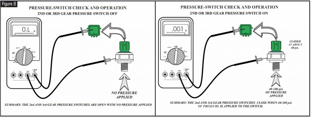
The PCM uses the mainshaft and countershaft speed-sensor information, the second- and third-clutch pressure switches, and the vehicle-speed sensor to calculate overlap on shifts as well as gear ratios. The PCM controls two different pressure modes. The first is CPC (clutch-pressure-control) mode, which is used during a gear change. This reduced-pressure mode makes it possible for two different clutch packs to be partially applied at the same time. The second is line-pressure mode, which is used to hold the clutch that is applied fully on. The 2nd- and/or 3rd-gear pressure switch, if the vehicle is so equipped, tells the PCM when the 2nd or 3rd clutch is starting to apply, or when that particular clutch is nearly released.
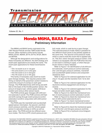
Refer to Figure 1 for identification of all shift-control solenoids, clutch-pressure-control solenoids, 2nd- and 3rd-gear pressure switches, mainshaft and countershaft speed sensors and component resistance chart.
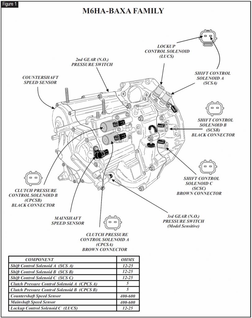
Refer to Figure 2 for solenoid application for driving in 1st gear and the transition from 1st to 2nd gear.
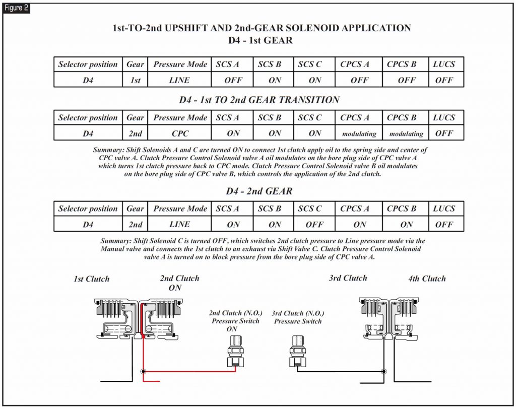
Refer to Figure 3 for solenoid application for the neutral-to-reverse engagement and driving in reverse.
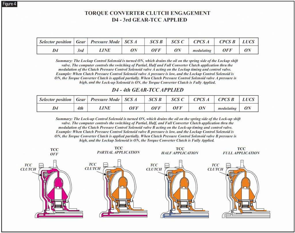
Refer to Figure 4 for solenoid application for the torque-converter-clutch apply stages.
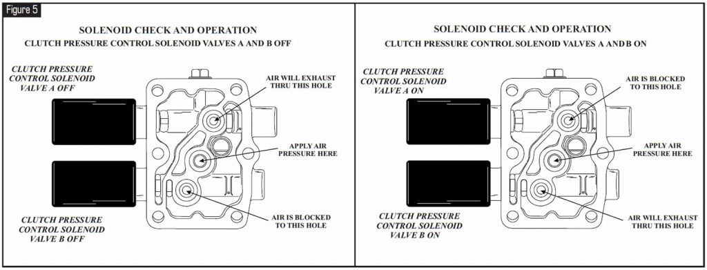
Refer to Figure 5 to check the mechanical function of clutch-pressure-control solenoids A and B.
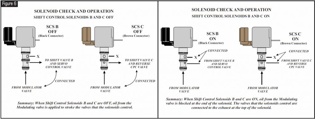
Refer to Figure 6 to check the mechanical function of shift control solenoids B and C.
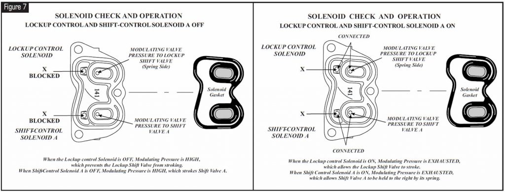
Refer to Figure 7 to check mechanical function of lockup-control solenoid and shift-control solenoid A.
Refer to Figure 8 to check the mechanical operation of the 2nd- and 3rd-gear pressure switches.
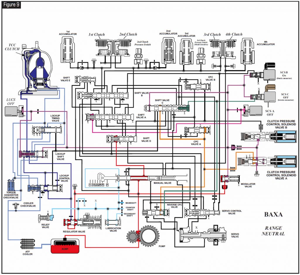
Refer to Figure 9 for a hydraulic-circuit diagram of the BAXA.


January 2004 Issue
Volume 21, No. 1
- Honda M6HA, BAXA Family: Preliminary Information


