Up to Standards
- Author: Mike Weinberg, Rockland Standard Gear, Contributing Editor
- Subject: Internal components
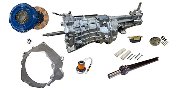
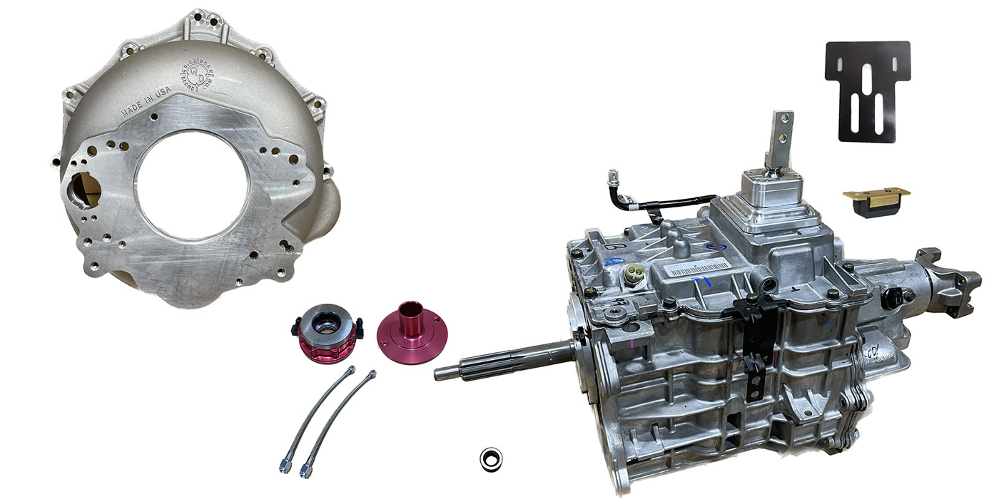
- Unit: Tremec TR6070
- Vehicle Application: 2014 Corvette Stingray
- Essential Reading: Rebuilder, Diagnostician
Last month we looked at the new C7 generation of Chevrolet Corvette, which brings the famous “Stingray” name back into use. GM has invested tremendous amounts of labor and capital to create a real world-class new model, which will be the first to use the new Tremec TR6070 seven-speed manual transmission. The new Stingray’s advanced computer controls will enable the driver to tune the vehicle to a number of driving modes, and Tremec did a really first-class design to provide seven speeds in a package that is only slightly different in size from the previous TR6060.
In this article we will explore the internals of the gearbox to prepare us for the coming generation of automatic and manual transmissions that have six, seven, eight or more speeds, reflecting the manufacturers’ push for improved fuel efficiency to comply with stricter federal requirements on the horizon.
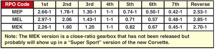
The TR6070 seven-speed gearbox will have several ratio options that are based on GM RPO codes for vehicle orders by the dealer from the factory.
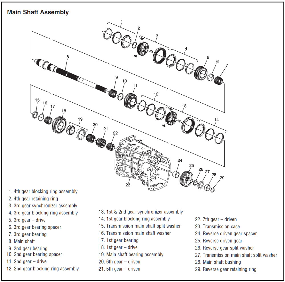
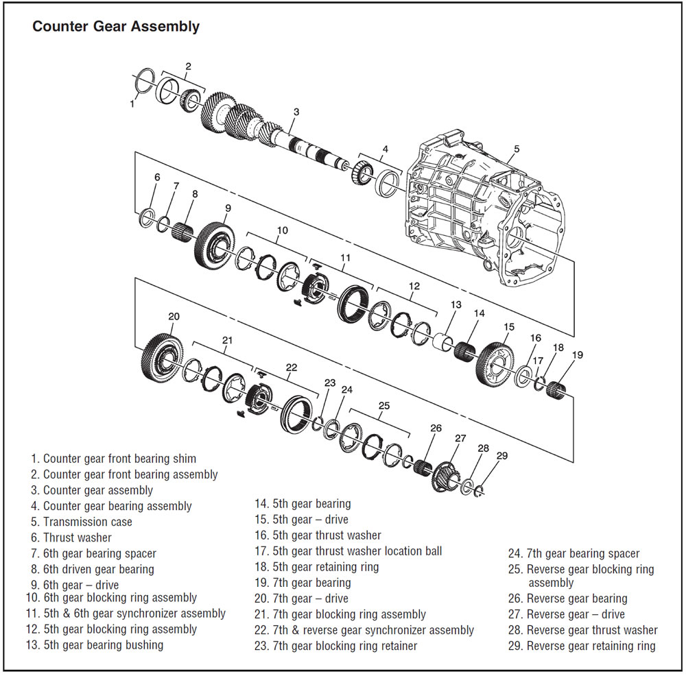
The synchronizers on these units are gear specific and must not be interchanged or flipped over. The seven-speed TR6070 uses “hybrid” synchronizer rings that are a combination of sintered-metal and carbon-fiber material for improved shifting and durability. First and second gears use triple-cone hybrid rings; third, fourth, fifth and sixth gears use double-cone hybrid rings; and reverse uses double-cone sintered-bronze rings.
A good habit to get into is to match-mark the synchronizer hub to sliding sleeve upon the start of disassembly from the shaft. Using an engraving tool or carbide bit, make a mark on the hub continuing onto the sliding sleeve. This allows you to disassemble the synchronizer components for inspection and cleaning and then reassemble them in their original mating condition and orientation (which side of the sleeve faces which gear). This prevents inducing a new wear pattern into the assembly, which will result in notchy shifts, and allows you to make sure which side of the slider faces the correct speed gear to prevent annoying comebacks.
These synchronizers use the same synchro struts with spring-loaded balls as those in the six-speed TR6060, which were a major improvement in durability and shift feel over the previous T56 spring-and-key design. The specs for measuring the gap between the synchro-ring bottom and the top of the engagement teeth are 0.037-0.078 inch for first and second, 0.035-0.080 inch for third and fourth gears, and 0.036-0.080 inch for fifth, sixth, seventh and reverse gears. When measuring the reverse-gear clearance make sure to remove the wave washer from the cone of reverse gear.
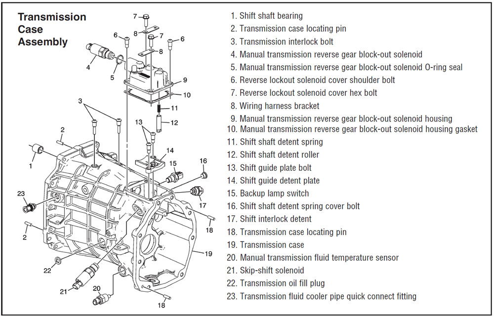
The TR6070 includes a number of computer controls. On the driver side of the case just below the shift tower is the “skip-shift” solenoid. In an attempt to produce better fuel efficiency and to comply with the federal fuel-economy standards, the PCM is capable of inhibiting shifts to second and third gears. If the driver tries to shift from first to second under conditions outside the computer parameters, the skip shift will force a shift from first to fourth gear. The conditions for the skip shift to actuate are coolant temperatures above 169°F, vehicle speed of 15-19 mph, a throttle opening of 21% or less and barometric pressure greater than 76 kPa (11 psi).
Automatic transmissions shift at open throttle, but the driver has control with a manual transmission. If the driver is going to shift at light throttle as described in the previous paragraph, the unit will go 1 to 4. There is nothing wrong with the unit; the driver merely has to stop driving like grandma and open the throttle for the skip shift to cease and desist.
There is also a reverse-lockout system that will inhibit a shift from seventh gear to reverse at a speed above 3 mph. It is possible for the driver to hit reverse when attempting a downshift from seventh to sixth. This invariably produces some unwanted noise along with damage to the synchronizer and gears. A reverse-lockout solenoid is installed on the shift tower of the main transmission case. With the ignition in run, battery voltage is directed to the reverse-inhibit solenoid. At forward speeds above 3 mph, the control circuit to this solenoid is opened by the PCM, which mechanically blocks the shift lever from going to the reverse position.
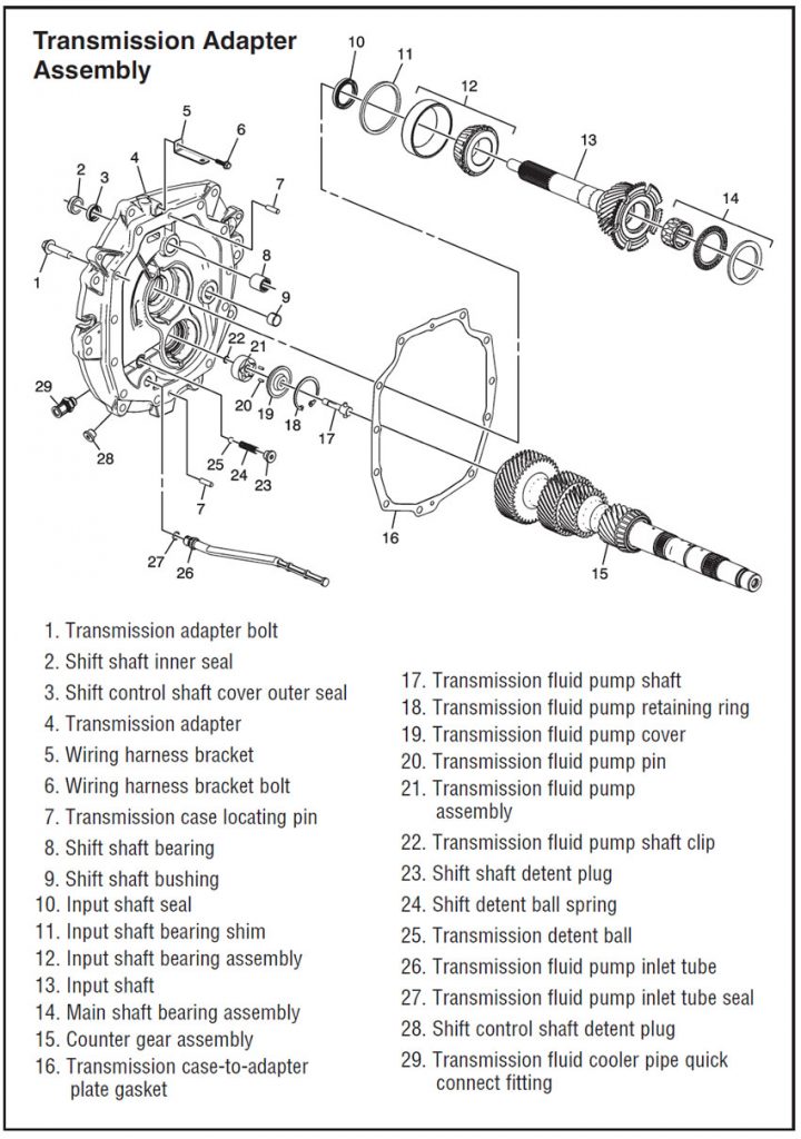
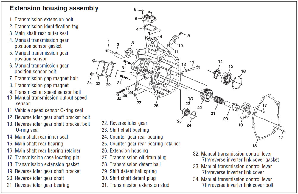
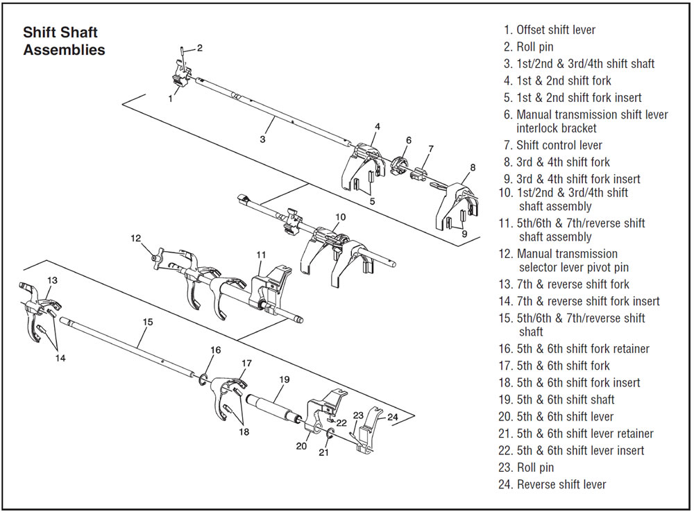
On the extension housing, we have a vehicle-speed sensor, a manual gear-position sensor, and a manual transmission control lever/seventh-reverse inverter link cover and assembly. On the end of the shift rail is a transmission gap magnet that the gear-position sensor uses to inform the PCM of the current position of the gear lever, so that the various mode controls can function correctly. This cover also allows easier assembly of the seventh/reverse shift fork.
One of the challenges a transmission manufacturer faces with any new design is to keep the package as small as possible. Tremec did this by changing the gear train on the TR6070 to move the fifth, sixth, seventh and reverse speed gears and synchronizers to the countershaft and move the opposing driven gears onto the mainshaft. Although Corvette production is not in huge numbers, this new design is a preview of how other designs will follow as the manufacturers comply with federal and state regulations and fight for market share.
One thing we know for sure: The only sure thing in the repair business is continual change. Being the guy who understands and embraces the design and engineering changes will make you the last guy standing, as more and more of your competitors fall by the wayside.

Mike Weinberg, Rockland Standard Gear, Contributing Editor.