
Torque Converter Tech Tips
- Author: Ed Lee
Impeller vanes
The movement of a vehicle relies on the torque converter’s ability to transfer the torque of the engine to the transmission (the beginning of the driveline).
Hydraulically speaking, movement starts with the first revolution of the engine, when the vanes of the torque-converter impeller start the oil moving toward the turbine. If the vanes become loose or fall out completely, the impeller loses its ability to move the oil and can no longer transfer torque. Converter rebuilders see the dramatic results of this when they cut open a converter and find that the impeller looks like a salad bowl. This is why checking and securing the vanes to the impeller is an important part of a quality rebuilt torque converter.
In the early years of torque converters, the impeller vanes were secured to the impeller by a secondary inner wall. This inner wall was sufficient to hold the vanes to withstand the torque of the engines of the day but was a nightmare for transmission rebuilders. At that time automatic-transmission fluid (ATF) was still in its primitive stages and was prone to shellacking. The fluid would cake up and become deposited in the cavity created by the inner wall. Technicians had to hold their breath every time the fluid was changed because there was always a risk that the new high-detergent fluid would dislodge a contaminant and cause a valve to stick in the valve body and/or governor.
The inner wall of the impeller was eliminated when the second generation of impeller vanes was introduced. The impeller walls were thicker and slots were machined into the impeller to secure the ends of the vanes. The vanes were held at the impeller wall by a staking procedure. The vanes also were held upright and rigid by a torus ring. There are two tabs at the center of each vane that pass through the torus ring and are folded over to secure the vanes to the ring. Any movement of this assembly will allow the vanes to become loose, so the assembly must be kept as rigid as possible.
As the torque of engines increased, the original-equipment manufacturers found it necessary to reinforce their converters. The GM 13-inch converters found in the LT 1 Corvettes and V-12 XJS Jaguars were reinforced by welding the impeller vanes to the impeller (see Figure 1). This process was unique because it was done from the outside of the impeller. During the weld process the dimple melted down, fusing the impeller to the vane. This process worked particularly well because it didn’t obstruct oil flow nor did it overheat the vane at the point of the weld. Some converter shops still reinforce their converters in a similar manner by using a TIG weld on the outside of the dimple area (see Figure 2).
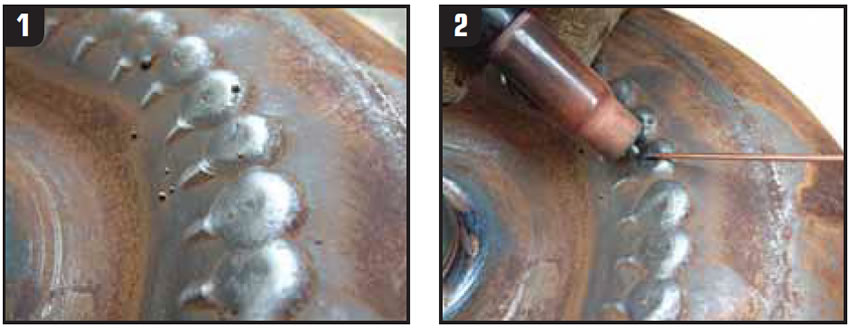
Today, most OEMs and some rebuilders reinforce the impellers by a furnace-brazing process. In the aftermarket, numerous other methods also can be found. Some rebuilders are brazing the ends of the vanes to the impellers by hand (see Figure 3).
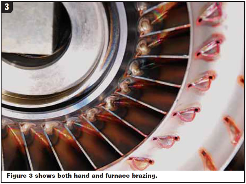
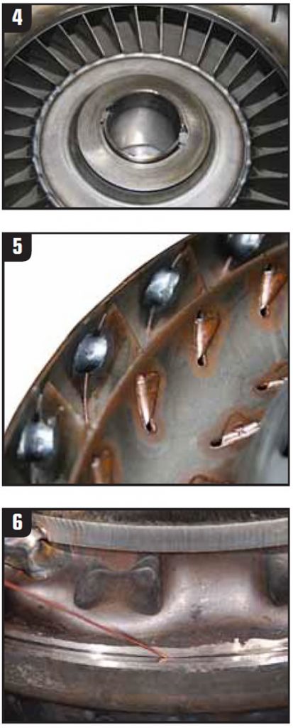
Some rebuilders are using a continuous MIG weld to reinforce the vanes, and others are using a MIG spot weld (see Figures 4 and 5).
Most rebuilders are dealing with the two tabs at the center of the vane where it meets the torus ring in some manner. Some are simply peening the tab to tighten the joint, but others have a wheeled fixture that both tightens and crimps the tabs in the same process. Some shops are either spot-welding or hand-brazing the tabs. The important part is that you are doing something to keep the vanes as rigid as possible.
Weld gaps
You have two very good reasons for paying attention to the gap between the cover and the impeller before completing the weld process. First, the gap has an effect on the alignment or runout of the converter. Second, contaminants can get into the converter during the weld process. It’s important that there be some gap between the mating parts before the weld process is started. If the cover and impeller do not rotate freely and independently of each other, they will not be in alignment after the weld process. It is equally important that this gap be kept to a minimum.
Consider that on most OEM converters this gap averages about 0.006 inch and the largest gap on any OEM converter blueprint is 0.010 inch. (Of course, when the OEM is welding the converter together, the mating parts are virgin and straight and have not been subjected to the operating stresses that rebuilders have to deal with.) The geometric form that holds the most volume per given surface area is the circle or ball, and that is the shape that the internal forces or pressures are trying to force the converter into.
You can see the effects that these forces have on the converter by measuring the diameter of the converter before and after it is cut apart. You will see that the diameter of the converter next to the weld is up to 0.020 inch larger after it is cut apart. This natural ballooning, plus the cleanup machine work necessary to dress the mating parts, accounts for the wider gap. Keeping the weld gap to 0.020 inch or less would be ideal, but most shops allow up to a 0.035-inch gap. Many shops will use a short length of 0.035-inch welding wire as a “go, no-go” gauge (see Figure 6).
When the weld gap becomes excessive, your chances increase that the total indicator runout (TIR) will not be within specification and that contaminants will get inside the converter during the weld process. These chances increase even more as the margin on the converter narrows. As far as the alignment is concerned this is true with all converters, but with contamination there is one exception. The Chrysler converters, which are built with the impellers resting on a step in the cover, virtually seal the path that would normally allow contaminants to enter the converter. You should still keep your weld gap to a minimum on these converters to keep them running true.

Ed Lee is a Sonnax technical specialist who writes on issues of interest to torque-converter rebuilders. Sonnax supports the Torque Converter Rebuilders Association. Learn more about the group at www.tcraonline.com. ©2008 Sonnax


