Up to Standards
- Author: Mike Weinberg, Contributing Editor
- Subject Matter: Manual transmission
- Issue: Operating theory & diagnosis
The auto-repair industry has undergone huge changes in recent years. The technology is changing and advancing by the minute. Vehicle build quality is unbelievably good, lowering the need for repairs. The proliferation of transmissions and transfer cases from a few models to a cast of thousands continues as the technology and demands of the public force ever more evolution of design.
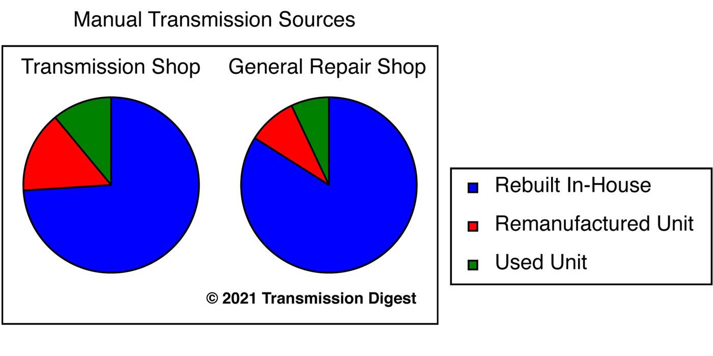
The transmission shop as a specialized business model has changed, and the number of shops doing only transmission work has declined dramatically as economics forces shops to do general-repair work to increase cash flow, just as general-repair shops are now doing more transmission work for the same reason. Production rebuilding has made transmissions, transfer cases, differentials etc. available to everyone through the car dealer or large remanufacturing plants.
What has not changed at all is the need for education. To achieve a specific skill set one must start with a good working knowledge of what they wish to accomplish. Diagnostic and repair skills are based on understanding the theory of operation of the product. It is absolutely impossible to diagnose any vehicular problem without a complete understanding of how it operates, its design parameters and which related systems affect the operation. For example, we have people employed in factories as assemblers. They put parts together in a component in an ordered fashion to complete a product hundreds or thousands of times a day. They surely know where the parts go and the specifications for the finished product.
Can these people who surely know the product from start to finish diagnose and repair what they are working on? No, they cannot. The person who can efficiently repair a problem component can do so only by knowing its operational theory, how the parts work together and all the related systems in the vehicle that can affect the component. Designs vary in size and shape, number of speeds and torque capacity, but they all work the same way. The difference between an assembler and a technician is the knowledge of how the design is intended to work. We speak with a growing number of people who are repairing or replacing transmissions and transfer cases but have limited or no knowledge as to how they operate. This article will speak to how things work, which is the first step toward having a base of understanding diagnostics and problem solving.

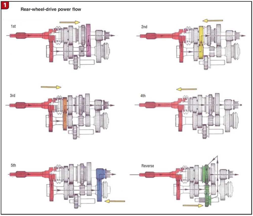
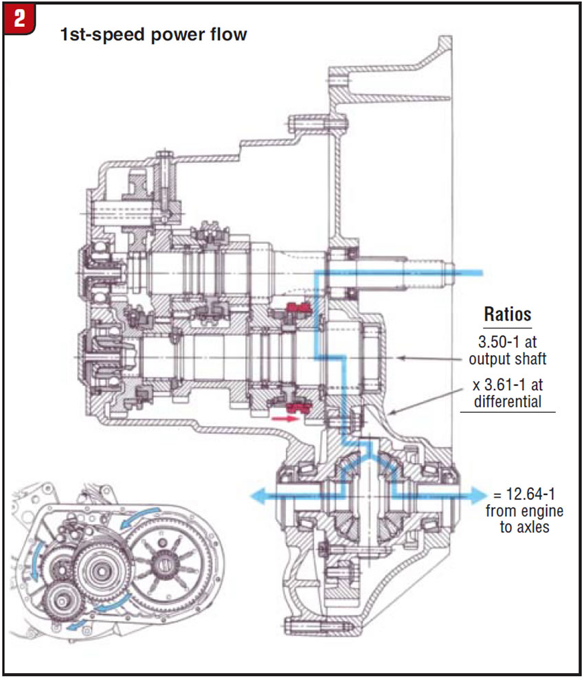
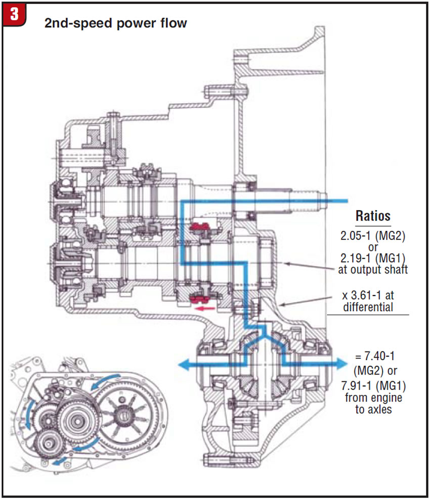
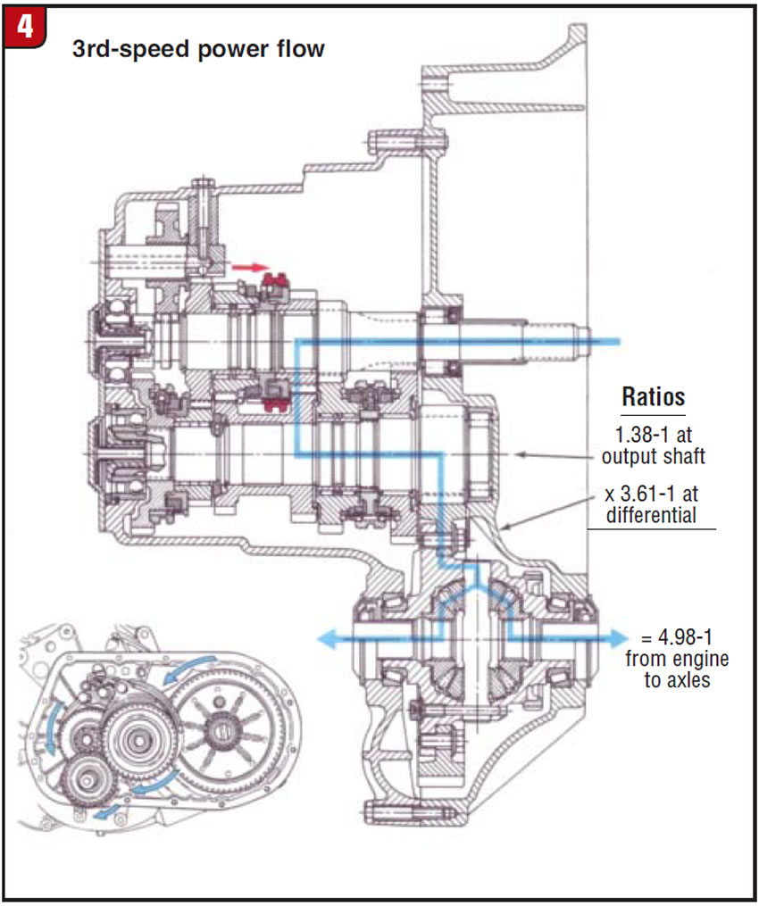
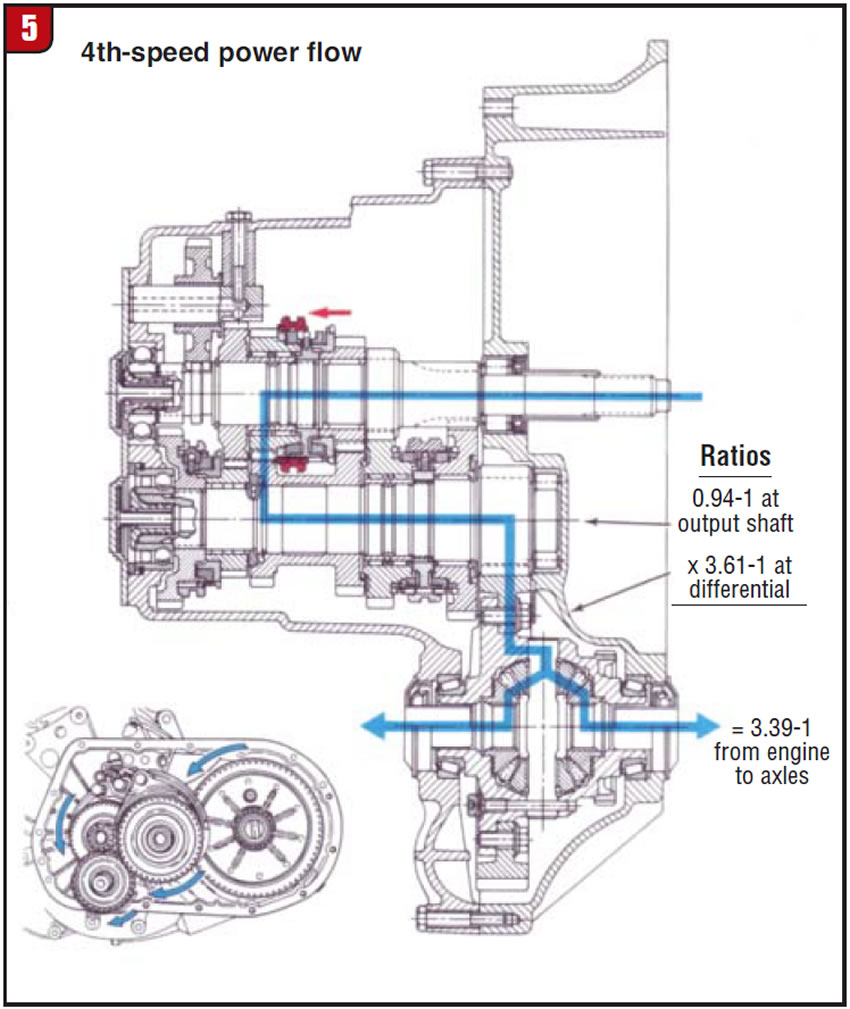
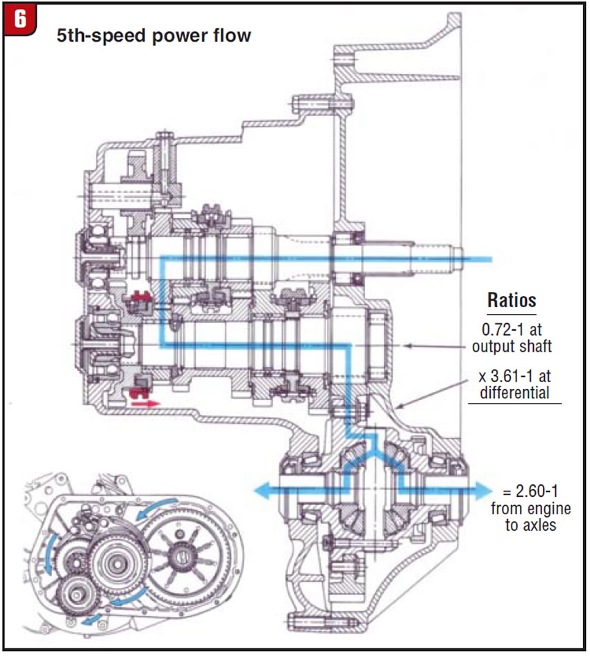
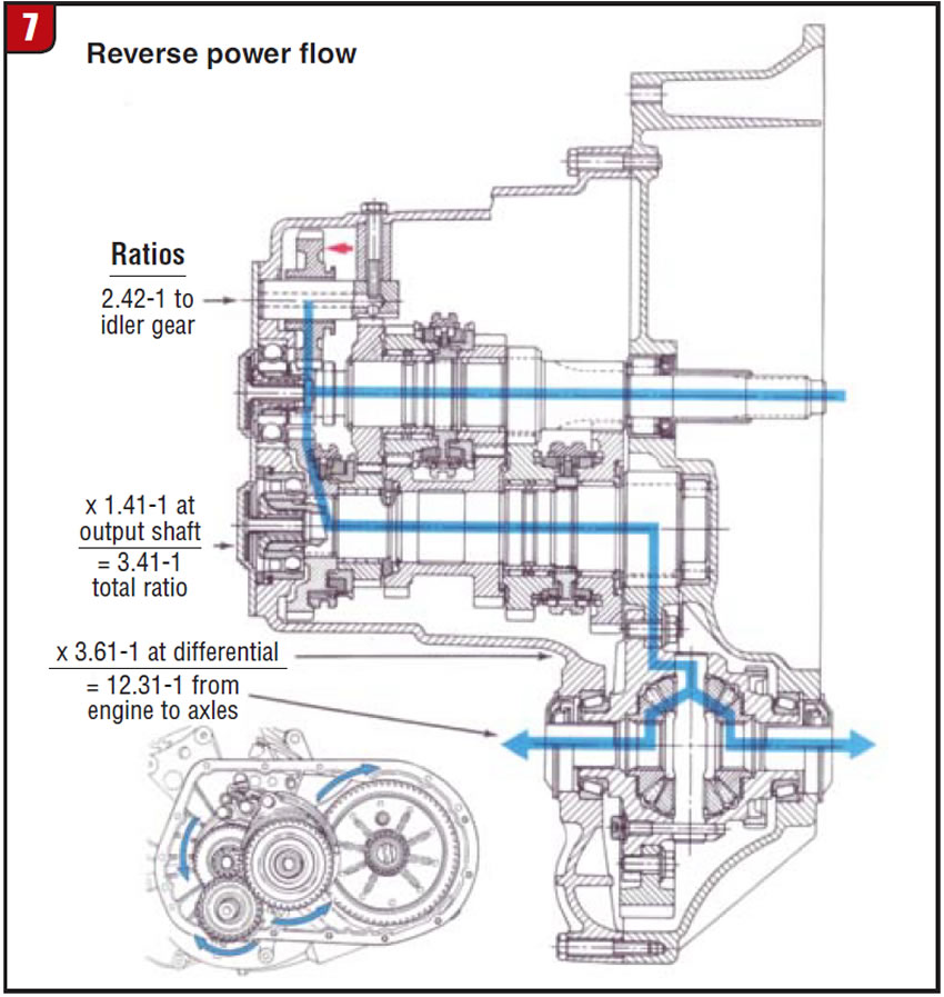
Manual transmissions – whether three-speed or 16-speed units, rear- or front-wheel-drive – all work the same way. To be usable, the engine’s torque must be broken down into manageable steps or speeds. The result is a set of gear ratios allowing the vehicle to go from a dead stop to road speeds fuel-efficiently. The first-gear ratio will be high enough numerically to move the vehicle’s weight from stop to go. The next sets of gears will have descending numerical ratios to increase vehicle speeds smoothly while increasing fuel efficiency. Figures 1-7 illustrate power flow in each of the gear ratios in front- and rear-wheel-drive transmissions.
If it takes, say, 250 lb.-ft. of torque to overcome a vehicle’s inertia and move it from a dead stop, just a small amount of torque can maintain highway speed on flat ground.
Automatic transmissions shift at open throttle; manual transmissions shift at closed throttle.
There are two disconnects in a manual transmission to decouple engine power from the transmission. The first is the clutch, which when working properly completely disconnects the engine torque from the input to the transmission. The second disconnect occurs inside the transmission as the input shaft is not directly coupled to the output shaft unless a gear is selected. This gives the transmission a neutral position that allows the engine to transmit power through the clutch into the transmission without driving the drive wheels. In the neutral position the input shaft is turning at engine speed and is driving the countershaft (cluster gear). Because no gear has been selected there is no power flowing to the output shaft (mainshaft) of the transmission, because none of the synchronizer sliding sleeves is in position to couple the output shaft to the speed gears and send power to the drive wheels.
When the input shaft is directly coupled to the output shaft, the transmission is in direct drive with no power flowing through the countershaft. Typically this will be fourth or fifth gear in modern transmissions. Without an understanding of power flow and operating theory it is doubtful that a proper diagnosis can take place. Knowing what we just spoke about here, if a transmission came to you that would move only in fourth gear (direct drive) but no other gears, it would be obvious that the input could not transfer power to the countergear because of either broken teeth that mesh the two gears or a broken countershaft.
The next area of understanding that must be achieved is synchronization (Figure 8). To achieve smooth, clash-free shifts, the sliding sleeve must mate with the speed gear to be selected. To mate two components that are spinning at different speeds, their speeds must be matched. In earlier transmissions that were not synchronized in some gears, the driver had to double-clutch and blip the throttle to match engine speed to the output-shaft speed. Remember that during a shift, the clutch is disengaged and the drive wheels are turning the output shaft at road speed while engine speed has basically moved toward idle.
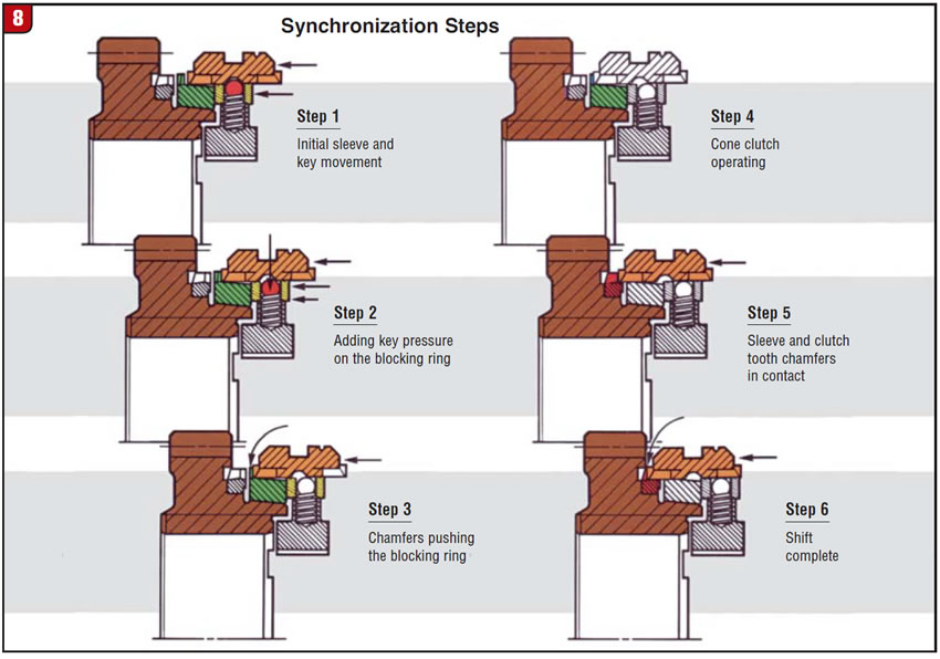
The synchronizer assembly uses a synchronizer or blocking ring as a wet clutch to grab the cone of the desired speed gear and speed it up or slow it down (upshift or downshift) until it matches the speed of both components. When this parity in speeds is achieved the synchronizer ring will relax and permit the sliding sleeve to lock to the engagement teeth on the speed gear without any grinding or block-out.
There is a “back taper” cut into the engagement teeth on the speed gear and on the sliding sleeve to hold the sleeve in place under changing throttle loading, preventing the gear from hopping out. Again, without the proper education we have people ordering a new set of synchro rings to cure a gear jump-out problem. A worn or cracked ring will cause only grinding; notchy, hard shifts; or a block-out preventing gear engagement. Gear jump-out occurs only from worn-out back taper on the speed gear and sleeve, or excessive endplay on the shaft that will allow the components to move out from the position where the sleeve is holding the gear.
I have seen many people try to stiffen the detent springs on the shift rail to hold a selected gear. The springs on the shift-rail detents are there only to give the driver a positive feel for the shifter position and are not capable of holding a worn gear and slider in place. Again, ignorance becomes expensive.
Front- or rear-wheel-drive, three-speeds and up, they all work the same way. Under throttle with an engaged clutch, engine torque flows into the transmission. When the clutch is depressed, engine torque is disconnected from the transmission and the drive wheels are turning the output shaft at road speed. Differentials, transfer cases and transmissions are all the same; unless you have a clear understanding of how it is supposed to work you can’t diagnose the problem. The repair manual will show you where all the parts go; the theory of operations changes the man from an assembler to a technician.
Mike Weinberg is president of Rockland Standard Gear.